UC-7400 specifications
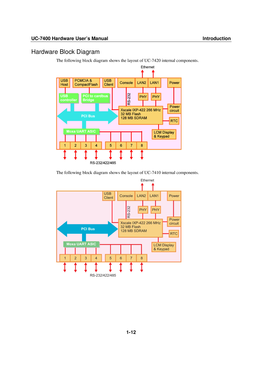
Moxa Technologies is renowned for its advanced industrial networking solutions, and the UC-7400 series exemplifies their commitment to reliability, versatility, and cutting-edge performance in edge computing applications. The UC-7400 is a compact and robust computing platform designed for a variety of industrial environments. It is ideal for data acquisition, protocol conversion, and remote monitoring solutions, among other uses.One of the main features of the UC-7400 is its support for multiple communication protocols. It integrates seamlessly with various data sources, such as PLCs, sensors, and other field devices, supporting commonly used protocols like Modbus, MQTT, and TCP/IP. This versatility allows users to easily connect to a diverse range of devices, facilitating quick and efficient data collection.
The UC-7400 is equipped with a powerful ARM-based processor, providing reliable performance while ensuring energy efficiency. Its compact design makes it suitable for applications where space is limited, and the unit can operate effectively in a wide temperature range, making it resilient in harsh environments often found in industrial settings. The rugged design enhances its durability, ensuring that it can withstand the challenges of various operational conditions.
Another standout characteristic of the UC-7400 series is its scalability. The platform includes multiple I/O options, enabling users to expand functionality according to their specific needs. Additionally, it offers a flexible operating system support, running on both Linux and Windows, which allows developers to use their preferred software development tools and create custom applications seamlessly.
Furthermore, Moxa Technologies has incorporated advanced security features into the UC-7400 series. Built-in security protocols help protect sensitive data during transmission and ensure the integrity of the system from potential cyber threats. This focus on security is particularly crucial for industrial IoT applications, where data breaches can lead to significant operational disruptions.
The UC-7400 series also supports various connectivity options, including Ethernet, Wi-Fi, and cellular networks, allowing robust and flexible integration with cloud services. This feature positions it as an ideal choice for edge computing and remote monitoring solutions, enabling real-time data access and better decision-making.
In summary, the Moxa Technologies UC-7400 series stands out with its multi-protocol support, robust hardware design, scalable architecture, enhanced security features, and versatile connectivity options. Businesses looking to enhance their industrial automation and IoT initiatives will find the UC-7400 an invaluable asset in optimizing their operations and harnessing the full potential of their data-driven strategies. Its combination of features makes it a reliable choice for a wide range of industrial applications.

