Manuals
/
Mr. Heater
/
Household Appliance
/
Electric Heater
Mr. Heater
MH9BX
owner manual
Maintenance, Troubleshooting Information
Models:
MH9BX
1
6
8
8
Download
8 pages
20.52 Kb
1
2
3
4
5
6
7
8
Troubleshooting
Parts list
Page 6
Image 6
Page 5
Page 7
Page 6
Image 6
Page 5
Page 7
Contents
OPERATING INSTRUCTIONS AND OWNER’S MANUAL
GENERAL SAFETY INSTRUCTIONS
CONTENTS
SPECIFICATIONS
THE STATE OF CALIFORNIA REQUIRES THE FOLLOWING WARNING
ODOR FADING ‑ NO ODOR DETECTED
ODOR FADE WARNING
FUEL GAS ODOR
ATTENTION ‑ CRITICAL POINTS TO REMEMBER
GENERAL INFORMATION
Figure 4 Release knob
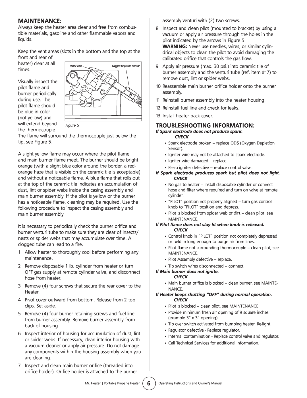
MAINTENANCE
TROUBLESHOOTING INFORMATION
Mr. Heater Portable Propane Heater Model # MH9BX
REPLACEMENT PARTS LIST
ACCESSORIES ITEM # DESCRIPTION
Part#
MH9BX
OPERATING INSTRUCTIONS Model #
PARTS ORDERING INFORMATION
Heaters with
Top
Page
Image
Contents