SECTION 2: ASSEMBLING YOUR TILLER

NOTE: This operator’s manual covers various models of tillers. The units illustrated may vary slightly from your unit. Follow only those instructions which pertain to your model number.

NOTE: References to right or left side of the tiller are determined from behind the unit in the operating position.

To Remove Unit From Carton

Remove staples, break glue on top flaps, or cut tape at carton end and peel along top flap to open carton.

Remove loose parts included with unit (i.e., operator’s manual, etc.).

Cut corners and lay carton down flat.

Remove packing material.

Roll or slide unit out of carton. Check carton thoroughly for loose parts.

Extend control cable and lay on the floor. Be careful not to bend or kink control cable.

IMPORTANT: This unit is shipped without gasoline or oil in the engine. Be certain to service engine with gasoline and oil as instructed in the separate engine manual before operating your machine.

Loose Parts In Carton

Depth Stake

Handle Assembly

Shift Rod

NOTE: All hardware needed for assembly is attached to the loose parts or the tiller.

Before Assembly

WARNING: Disconnect the spark plug wire and ground it against the engine to prevent unintended starting.

Attaching Depth Stake

Tip the tiller forward so it rests on front counterweight.

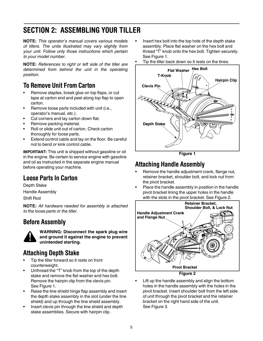
Unthread the “T” knob from the top of the depth stake and remove the flat washer and hex bolt. Remove the hairpin clip from the clevis pin.

See Figure 1.

Raise the tine shield hinge flap assembly and insert the depth stake assembly in the slot (under the tine shield) and up through the tine shield assembly.

Insert clevis pin through the tine shield and depth stake assemblies. Secure with hairpin clip.

Insert hex bolt into the top hole of the depth stake assembly. Place flat washer on the hex bolt and thread “T” knob onto the hex bolt. Tighten securely. See Figure 1.

Tip the tiller back down so it rests on the tines.

Flat Washer

Hex Bolt

T-Knob


Hairpin Clip

Clevis Pin


Depth Stake


Figure 1

Attaching Handle Assembly

Remove the handle adjustment crank, flange nut, retainer bracket, shoulder bolt, and lock nut from the pivot bracket.

Place the handle assembly in position in the handle pivot bracket lining the upper holes in the handle with the slots in the pivot bracket. See Figure 2.

Retainer Bracket,

Shoulder Bolt, & Lock Nut

Handle Adjustment Crank

and Flange Nut

Pivot Bracket

Figure 2

Lift up the handle assembly and align the bottom holes in the handle assembly with the holes in the pivot bracket. Insert shoulder bolt from the left side of unit through the pivot bracket and the retainer bracket on the right hand side of the unit.

See Figure 3.

5

Page 5
Image 5
MTD 410 Series manual Assembling Your Tiller, To Remove Unit From Carton, Loose Parts In Carton, Attaching Handle Assembly

410 Series specifications

The MTD 410 Series represents a significant advancement in outdoor power equipment, designed specifically for demanding users who require reliability and efficiency in their tools. Engineered for both residential and light commercial use, the MTD 410 Series showcases a blend of robust performance and user-friendly features, making it a popular choice among landscapers, gardeners, and homeowners alike.

One of the standout features of the MTD 410 Series is its powerful engine. Equipped with a high-performance four-stroke engine, these machines deliver consistent power and torque, allowing users to tackle various tasks such as mowing, trimming, and clearing debris with ease. The engine is designed for fuel efficiency, helping users to save on fuel costs while minimizing their environmental footprint.

The MTD 410 Series incorporates advanced cutting technology, allowing for precision mowing and trimming. With adjustable cutting heights, users can achieve the perfect lawn finish, whether they prefer a close cut or a more relaxed mowing height. Additionally, the series includes features such as mulching capabilities, allowing grass clippings to be finely chopped and returned to the lawn as natural fertilizer, promoting healthier grass growth.

Durability is another hallmark of the MTD 410 Series. Constructed from high-quality materials, these machines are built to withstand the rigors of outdoor use. The reinforced chassis and robust components ensure longevity, reducing the need for frequent repairs or replacements. Furthermore, the series is designed with ease of maintenance in mind, featuring accessible engine components and an intuitive design that makes routine upkeep straightforward.

Ergonomics plays a crucial role in the overall user experience of the MTD 410 Series. With adjustable handles and user-friendly controls, operators can comfortably maneuver the machines over various terrains. The lightweight design also contributes to easy handling, making it possible for users of all skill levels to operate the equipment effectively.

In terms of technology, the MTD 410 Series often features electric start options, eliminating the hassle of manual starting and making it even more convenient to use. Safety features like blade brakes and protective shields ensure a secure operating environment, allowing users to focus on their tasks with peace of mind.

Overall, the MTD 410 Series stands out due to its performance, durability, and user-centric design. It caters to a diverse range of outdoor tasks, making it an excellent investment for anyone looking to enhance their yard work or landscaping projects. Whether you're a seasoned professional or a weekend warrior, the MTD 410 Series equips you with the tools necessary to achieve outstanding results.