6

Maintaining

Your Snow

Thrower

WARNING

Before lubricating, repairing or inspecting, disengage all controls and stop engine. Wait until all moving parts have come to a complete stop. Remove the safety key to prevent unintended firing of the engine.

IMPORTANT

Refer to the Final Adjustment section of the Set-Up instructions after replacing drive and auger belts.

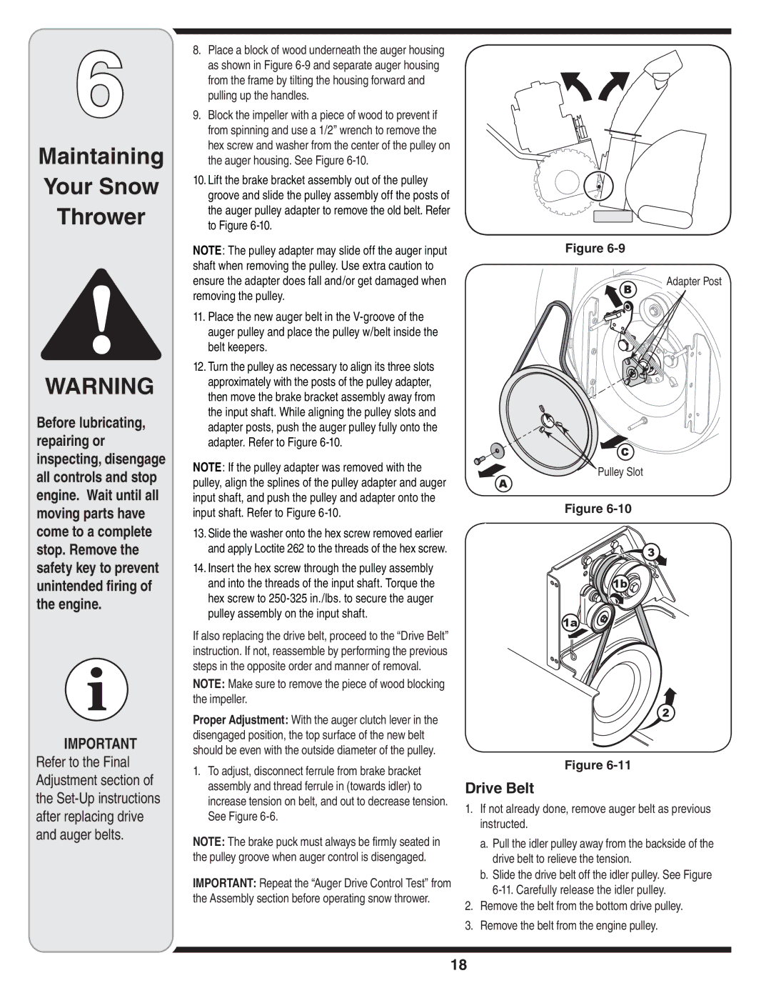
8.Place a block of wood underneath the auger housing as shown in Figure 6-9 and separate auger housing from the frame by tilting the housing forward and pulling up the handles.

9.Block the impeller with a piece of wood to prevent if from spinning and use a 1/2” wrench to remove the hex screw and washer from the center of the pulley on the auger housing. See Figure 6-10.

10.Lift the brake bracket assembly out of the pulley groove and slide the pulley assembly off the posts of the auger pulley adapter to remove the old belt. Refer to Figure 6-10.

NOTE: The pulley adapter may slide off the auger input shaft when removing the pulley. Use extra caution to ensure the adapter does fall and/or get damaged when removing the pulley.

11.Place the new auger belt in the V-groove of the auger pulley and place the pulley w/belt inside the belt keepers.

12.Turn the pulley as necessary to align its three slots approximately with the posts of the pulley adapter, then move the brake bracket assembly away from the input shaft. While aligning the pulley slots and adapter posts, push the auger pulley fully onto the adapter. Refer to Figure 6-10.

NOTE: If the pulley adapter was removed with the pulley, align the splines of the pulley adapter and auger input shaft, and push the pulley and adapter onto the input shaft. Refer to Figure 6-10.

13.Slide the washer onto the hex screw removed earlier and apply Loctite 262 to the threads of the hex screw.

14.Insert the hex screw through the pulley assembly and into the threads of the input shaft. Torque the hex screw to 250-325 in./lbs. to secure the auger pulley assembly on the input shaft.

If also replacing the drive belt, proceed to the “Drive Belt” instruction. If not, reassemble by performing the previous steps in the opposite order and manner of removal.

NOTE: Make sure to remove the piece of wood blocking the impeller.

Proper Adjustment: With the auger clutch lever in the disengaged position, the top surface of the new belt should be even with the outside diameter of the pulley.

1.To adjust, disconnect ferrule from brake bracket assembly and thread ferrule in (towards idler) to increase tension on belt, and out to decrease tension. See Figure 6-6.

NOTE: The brake puck must always be firmly seated in the pulley groove when auger control is disengaged.

IMPORTANT: Repeat the “Auger Drive Control Test” from the Assembly section before operating snow thrower.

Figure 6-9

B

Adapter Post


C

Pulley Slot

A

Figure 6-10

3

1b

1a

2

Figure 6-11

Drive Belt

1.If not already done, remove auger belt as previous instructed.

a.Pull the idler pulley away from the backside of the drive belt to relieve the tension.

b.Slide the drive belt off the idler pulley. See Figure 6-11. Carefully release the idler pulley.

2.Remove the belt from the bottom drive pulley.

3.Remove the belt from the engine pulley.

18

Page 18
Image 18
MTD 769-04179 warranty Drive Belt, Pulley Slot

769-04179 specifications

The MTD 769-04179 is a powerful and versatile lawn mower designed to meet the needs of homeowners seeking efficiency, durability, and ease of use in lawn care. This model stands out in the competitive market of outdoor power equipment, equipped with a range of features that enhance performance and user experience.

One of the primary characteristics of the MTD 769-04179 is its robust engine. It boasts a reliable gas-powered engine that delivers impressive torque and cutting power. This engine is designed to handle various lawn conditions, making it suitable for small to moderate-sized yards. The mower’s cutting deck typically measures between 20 to 22 inches, allowing users to cover more area with each pass while maintaining precision cutting.

The MTD 769-04179 also integrates advanced cutting technologies. The mower features a 3-in-1 cutting system that allows users to mulch, bag, or side discharge grass clippings based on their preferences and lawn care needs. This capability not only promotes a healthier lawn but also offers flexibility in managing grass waste. The adjustable cutting height is another key attribute, enabling users to select the ideal grass length for their specific lawn type and conditions.

In terms of user comfort and convenience, the MTD 769-04179 is designed with an ergonomic handle, which reduces strain during extended mowing sessions. The 769-04179 model generally includes easy-to-access controls for the engine start, speed adjustments, and cutting height selection, ensuring a seamless user experience.

Durability is also a prominent feature of this lawn mower. The MTD 769-04179 is constructed with high-quality materials that withstand the rigors of regular lawn maintenance. Its sturdy wheels provide excellent traction and maneuverability across different terrains, making it effective on both flat and uneven surfaces.

Maintenance is simplified in the MTD 769-04179, with user-friendly features that include easy access to the spark plug and air filter. This accessibility encourages regular upkeep, ensuring the mower remains in optimal working condition over time.

Overall, the MTD 769-04179 is a reliable choice for homeowners seeking an efficient and easy-to-handle lawn mower. With its powerful engine, versatile cutting options, and user-friendly design, it offers excellent value for those dedicated to maintaining a healthy and beautiful lawn.