SECTION 2: ASSEMBLING YOUR SNOW THROWER
Unpacking from carton
•Cut along corners of the carton and lay it down flat. See Figure 1. Remove packing material.
•Remove any loose parts included with unit (i.e., operator’s manual, etc.).
•Roll unit out of carton. Check carton thoroughly for any remaining loose part.
Remove loose parts
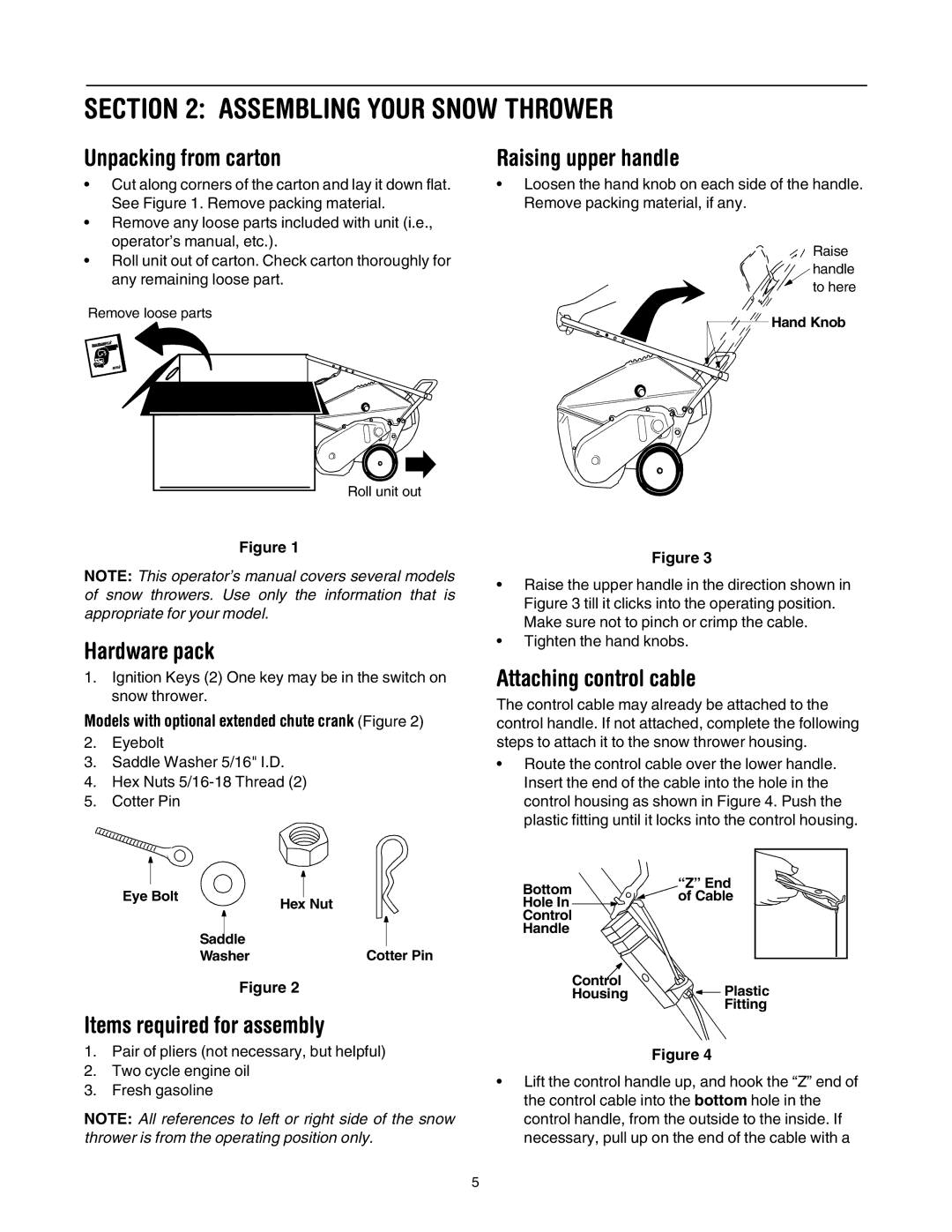
Raising upper handle
•Loosen the hand knob on each side of the handle. Remove packing material, if any.
Raise handle to here
![]() Hand Knob
Hand Knob
Roll unit out
Figure 1
NOTE: This operator’s manual covers several models of snow throwers. Use only the information that is appropriate for your model.
Hardware pack
1.Ignition Keys (2) One key may be in the switch on snow thrower.
Models with optional extended chute crank (Figure 2)
2.Eyebolt
3.Saddle Washer 5/16" I.D.
4.Hex Nuts
5.Cotter Pin
|
|
|
|
|
|
|
| |
|
|
|
|
|
|
|
| |
|
|
|
|
|
|
|
| |
|
|
|
|
|
|
|
| |
Eye Bolt |
|
|
|
|
| |||
Hex Nut | ||||||||
|
|
| ||||||
|
|
|
|
|
|
| ||
|
|
|
|
|
|
|
| |
|
|
|
|
|
|
|
| |
| Saddle |
|
|
|
|
| ||
| Washer |
|
|
| Cotter Pin | |||
Figure 2
Items required for assembly
1.Pair of pliers (not necessary, but helpful)
2.Two cycle engine oil
3.Fresh gasoline
NOTE: All references to left or right side of the snow thrower is from the operating position only.
Figure 3
•Raise the upper handle in the direction shown in Figure 3 till it clicks into the operating position. Make sure not to pinch or crimp the cable.
•Tighten the hand knobs.
Attaching control cable
The control cable may already be attached to the control handle. If not attached, complete the following steps to attach it to the snow thrower housing.
•Route the control cable over the lower handle. Insert the end of the cable into the hole in the control housing as shown in Figure 4. Push the plastic fitting until it locks into the control housing.
Bottom | “Z” End |
|
| ||||
of Cable |
|
| |||||
Hole In |
|
|
|
| |||
Control |
|
|
|
|
| ||
|
|
|
|
| |||
Handle |
|
|
|
|
| ||
Control |
|
|
|
|
| ||
|
| Plastic | |||||
Housing |
|
| |||||
|
| ||||||
|
|
|
|
| Fitting | ||
Figure 4
•Lift the control handle up, and hook the “Z” end of the control cable into the bottom hole in the control handle, from the outside to the inside. If necessary, pull up on the end of the cable with a
5