SECTION 6: MAKING ADJUSTMENT
WARNING: NEVER attempt to make any adjustments while the engine is running, except where specified in the operator’s manual.
Auger Control Adjustment
Refer to the information found under Final Adjust- ments in the Assembly Section to adjust the auger control.
Traction Control Adjustment
Refer to the information found under Final Adjustment in the Assembly Section to adjust the traction control. If you are uncertain that you have reached the correct adjustment, proceed as follows:
WARNING: Drain the gasoline out of the snow thrower’s tank, or place a piece of plastic film under the gas cap to avoid spillage BEFORE making the adjustment.
•Tip the snow thrower forward, allowing it to rest on the auger housing.
•Remove the frame cover underneath the snow thrower by removing the six
•With the traction control released, there must be clearance between the friction wheel and the drive plate in all positions of the shift lever.
•With the traction control engaged, the friction wheel must contact the drive plate. See Figure 14.
Gear Shaft | Drive |
Cable | |
Friction Wheel | Pivot Rod |
| |
Rubber |
|
| Drive |
| Plate |
Figure 14
If adjustment is necessary:
•Loosen the jam nut on the traction drive cable. Adjust the cable as necessary. Refer to Figure 8.
•Retighten the jam nut to secure the cable when correct adjustment is reached.
•Reassemble the frame cover.
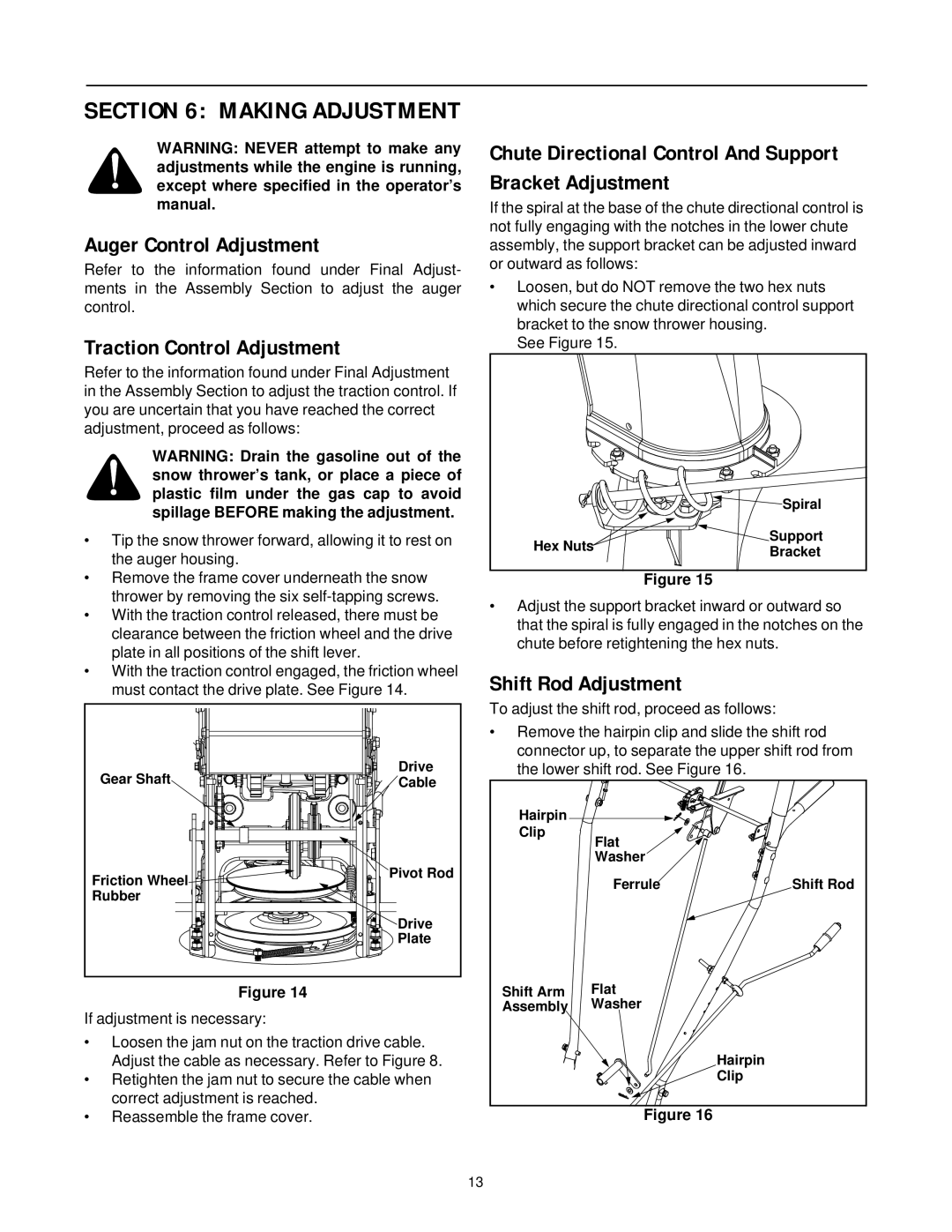
Chute Directional Control And Support Bracket Adjustment
If the spiral at the base of the chute directional control is not fully engaging with the notches in the lower chute assembly, the support bracket can be adjusted inward or outward as follows:
•Loosen, but do NOT remove the two hex nuts which secure the chute directional control support bracket to the snow thrower housing.
See Figure 15.
| Spiral | |
Hex Nuts | Support | |
Bracket | ||
|
Figure 15
•Adjust the support bracket inward or outward so that the spiral is fully engaged in the notches on the chute before retightening the hex nuts.
Shift Rod Adjustment
To adjust the shift rod, proceed as follows:
•Remove the hairpin clip and slide the shift rod connector up, to separate the upper shift rod from the lower shift rod. See Figure 16.
Hairpin |
|
|
Clip | Flat |
|
|
| |
| Washer |
|
| Ferrule | Shift Rod |
Shift Arm | Flat |
|
Assembly | Washer |
|
|
| Hairpin |
|
| Clip |
Figure 16
13