EXPLANATION OF FEATURES AND CONTROLS
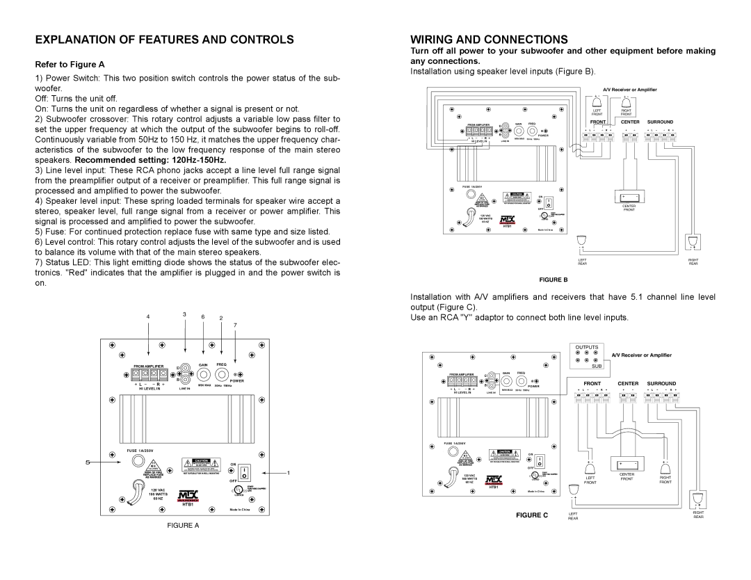
Refer to Figure A
1) Power Switch: This two position switch controls the power status of the sub- |
woofer. |
WIRING AND CONNECTIONS
Turn off all power to your subwoofer and other equipment before making any connections.
Installation using speaker level inputs (Figure B).
Off: Turns the unit off. |
On: Turns the unit on regardless of whether a signal is present or not. |
2) Subwoofer crossover: This rotary control adjusts a variable low pass filter to |
set the upper frequency at which the output of the subwoofer begins to |
Continuously variable from 50Hz to 150 Hz, it matches the upper frequency char- |
acteristics of the subwoofer to the low frequency response of the main stereo |
speakers. Recommended setting: |
3) Line level input: These RCA phono jacks accept a line level full range signal |
from the preamplifier output of a receiver or preamplifier. This full range signal is |
processed and amplified to power the subwoofer. |
4) Speaker level input: These spring loaded terminals for speaker wire accept a |
stereo, speaker level, full range signal from a receiver or power amplifier. This |
signal is processed and amplified to power the subwoofer. |
5) Fuse: For continued protection replace fuse with same type and size listed. |
6) Level control: This rotary control adjusts the level of the subwoofer and is used |
to balance its volume with that of the main stereo speakers. |
7) Status LED: This light emitting diode shows the status of the subwoofer elec- |
tronics. "Red" indicates that the amplifier is plugged in and the power switch is |
FROM AMPLIFIER | GAIN | FREQ | |
L |
| ||
|
| R | POWER |
L | R |
| |
MIN MAX | 50Hz 150Hz | ||
HI LEVEL IN | LINE IN |
| |
FUSE 1A/250V |
|
| |
|
|
| ON |
| 1A 250V |
|
|
|
|
| OFF |
| 120 VAC |
|
|
| 100 WATTS |
|
|
| 60 HZ |
|
|
|
| HTB1 |
|
|
|
| Made In China |
A/V Receiver or Amplifier | |||
+ - | + - |
|
|
LEFT | RIGHT |
|
|
FRONT | FRONT |
|
|
FRONT | CENTER | SURROUND | |
| + | - |
|
| CENTER |
|
|
| FRONT |
|
|
- + |
|
| - + |
LEFT |
|
| RIGHT |
REAR |
|
| REAR |
on. |
� | � | � | � |
| |||
|
|
| � |
FIGURE B
Installation with A/V amplifiers and receivers that have 5.1 channel line level output (Figure C).
Use an RCA "Y" adaptor to connect both line level inputs.
�������������� | ���� | ���� | |
� |
| ||
|
|
| |
|
| � | ����� |
|
|
| |
� | � | ������� | ���� ������ |
����������� | ������� |
| |
������������� |
|
| |
� |
|
| �� |
| �� ���� |
| � |
|
|
| |
|
|
| ��� |
| ������� |
|
|
| ��������� |
|
|
| ����� |
|
|
|
|
|
| OUTPUTS |
|
|
|
| SUB |
FROM AMPLIFIER | GAIN | FREQ |
| |
L |
|
| ||
|
| R | POWER | FRONT |
L | R |
|
| |
MIN MAX | 50Hz 150Hz |
| ||
HI LEVEL IN | LINE IN |
|
| |
FUSE 1A/250V |
|
|
| |
|
|
| ON |
|
| 1A 250V |
|
|
|
|
|
|
| + - |
|
|
| OFF |
|
| 120 VAC |
|
| LEFT |
| 100 WATTS |
|
| |
| 60 HZ |
|
| FRONT |
|
| HTB1 |
|
|
|
|
| Made In China |
|
- +
A/V Receiver or Amplifier
CENTER SURROUND
+ | - | + - |
CENTER
FRONTRIGHT FRONT
���� |
������������� |
�������� |
|
| - + |
FIGURE C | LEFT | RIGHT |
REAR | ||
| REAR |
|
