Installation Instructions
WARNING
Before beginning installation of this Murphy product:
✔Disconnect ALL electrical power to the machine.
✔Make sure the machine CANNOT operate during installation.
✔Follow all safety warnings of the machine manufacturer.
✔Read and follow all installation instructions.
1.Select a mounting location in lower part of the bilge for the MAC1 air cell, but do not mount cell at this time. MAC1 must be placed so that no debris will become trapped inside it. Position the air cell approximately
2.Mount the BLS1 switch via optional mounting bracket 15050737 or one of your supply. Keep the BLS1 switch within 4 ft. (1.21 m) off the MAC1 air cell. Tubing must NOT have a loop or flat area for moisture to collect. Always maintain a downward slope.
CAUTION: Air cell tubing and connections must remain air tight. Seal any holes placed in the air cell.
3.Attach the MACT1 tubing kit to the air cell and to the BLS1 switch. Any tubing can be used as long as it does not corrode and it provides air tight connec- tions.
4.Wire the SPDT
5.The BLS1 trip point is preset to operate when bilge level rises approximately
6.Raise or lower the air cell so that the distance from the hull to the trip point level on the side of the air cell is equal to desired level of bilge. Secure the air cell via the 2 hex bolts.
If necessary, adjustment can be made prior to installation by placing the air cell in a bucket of water and adjusting the white knurled knob inside the BLS1 until the
7.Verify proper operation at desired levels prior to launch.
NOTE: The air cell will automatically recharge itself anytime the bilge level falls below the air cell.
How to Order the BLSK1
To order use the model number designation diagram below.
BLSK1 


Base Model
BLS1 = Bilge level switch
BLSK1 = Bilge level switch kit:
BLS1 (Bilge Level Switch)
MACT1 (Tubing kit)
MAC1 (Air cell)
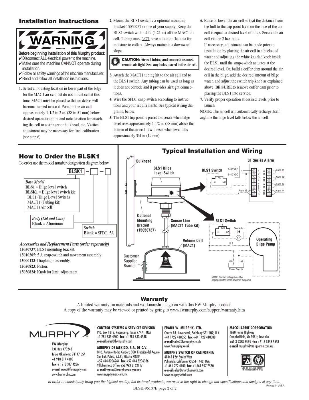
Typical Installation and Wiring
Bulkhead |
|
|
| ST Series Alarm |
| |
BLS1 Bilge | BLS1 Switch | + | 1 | A | Alarm #1 | |
Level Switch |
| – | 2 | B |
| |
| NO |
|
| 3 | A | Alarm #2 |
| C | NC |
| 4 | B |
|
|
| 5 | A | Alarm #3 | ||
|
|
|
| |||
|
|
|
| 6 | B |
|
|
|
| Alarm #5 | A | A | Alarm #4 |
|
|
|
| B | B |
|
Body (Lid and Case)
Blank = Aluminum
Switch
Blank = SPDT, 5A
Accessories and Replacement Parts (order separately)
15050737: BLS1 mounting bracket.
15010205: 5 A
15000123: Diaphragm assembly.
15050823: Piston.
15050824: Knob for limit adjustment.
Optional
Mounting
Bracket (15050737)
Customer
Supplied
Bracket ![]()
Sensor Line (MACT1 Tube Kit)
Volume Cell (MAC1)
AIR
BLS1 Switch
| NO |
| See Note |
|
|
CNC
| Operating | |
| ||
| Bilge Pump | |
|
|
+ve
Power Supply
NOTE: Contact rating should be appropriate for horse power of the pump.
Warranty
A limited warranty on materials and workmanship is given with this FW Murphy product.
A copy of the warranty may be viewed or printed by going to www.fwmurphy.com/support/warranty.htm
FW Murphy
P.O. Box 470248
Tulsa, Oklahoma 74147 USA +1 918 317 4100
fax +1 918 317 4266
CONTROL SYSTEMS & SERVICES DIVISION P.O. Box 1819; Rosenberg, Texas 77471; USA +1 281 633 4500 fax +1 281 633 4588
MURPHY DE MEXICO, S.A. DE C.V.
Blvd. Antonio Rocha Cordero 300, Fracción del Aguaje San Luis Potosí, S.L.P.; México 78384
+52 444 8206264 fax +52 444 8206336 Villahermosa Office +52 993 3162117
FRANK W. MURPHY, LTD.
Church Rd.; Laverstock, Salisbury SP1 1QZ; U.K. +44 1722 410055 fax +44 1722 410088
MURPHY SWITCH OF CALIFORNIA
41343 12th Street West
Palmdale, California 93551-1442; USA
+1 661 272 4700 fax +1 661 947 7570
MACQUARRIE CORPORATION 1620 Hume Highway Campbellfield, Vic 3061; Australia
+61 3 9358 5555 fax +61 3 9358 5558
| E |
|
| D |
|
|
| ||
| R |
|
|
|
|
|
| E |
|
| GISTER |
| ||
|
|
|
|
|
In order to consistently bring you the highest quality, full featured products, we reserve the right to change our specifications and designs at any time.
Printed in U.S.A.