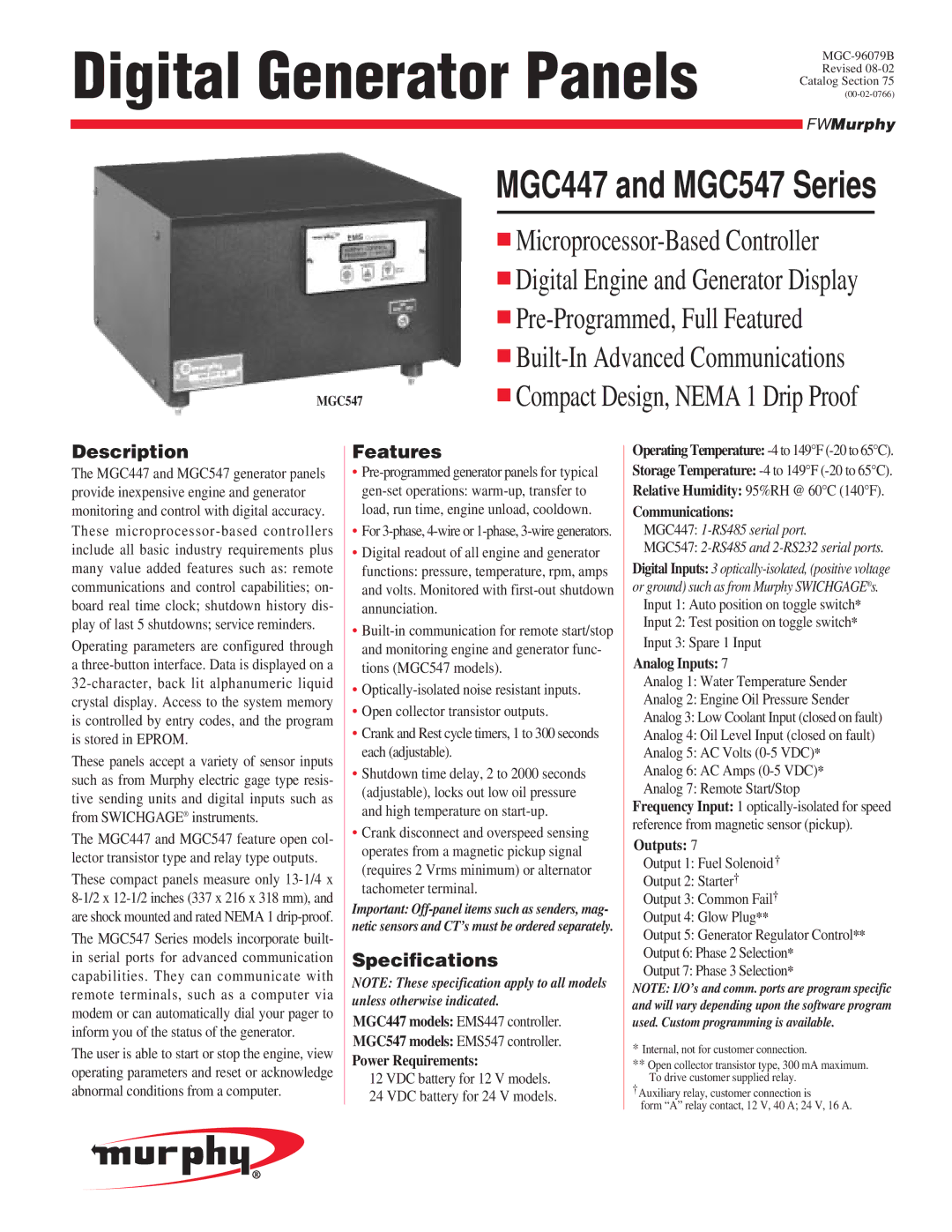
MGC447, MGC547 specifications
Murphy MGC447 and MGC547 are advanced monitoring and control systems designed for a wide variety of industrial applications. Both devices are engineered to enhance machinery performance, ensure operational safety, and facilitate effective management of critical parameters in real-time environments.The Murphy MGC447 offers robust monitoring capabilities, making it well-suited for applications such as diesel engines, compressors, and generators. It features a clear LCD display that provides users with an intuitive interface for reading critical information. This model is equipped with a variety of input options, enabling it to interface with multiple sensors and provide real-time data on engine temperature, pressure, and other operational metrics.
One of the standout features of the MGC447 is its versatility; it supports both analog and digital inputs. This flexibility allows operators to customize their monitoring system according to specific requirements. Additionally, it includes integrated alarm functions, which enhance safety by providing immediate notifications in case of abnormal conditions, thereby allowing for fast response times.
On the other hand, the MGC547 enhances these capabilities with advanced communication technologies. This model is designed for a more extensive range of applications and supports a variety of protocols, including Modbus. This integration enables seamless communication with other devices and systems, facilitating remote monitoring and control options. The MGC547 also features enhanced data logging capabilities, enabling users to store and retrieve historical operational data, which aids in performance analysis and troubleshooting.
Both systems are built for durability and reliability, featuring rugged construction suitable for harsh environments. They are designed to withstand extreme temperatures, vibrations, and moisture, ensuring consistent performance even in challenging conditions. The user-friendly interfaces simplify the setup and operation processes, making them accessible for both experienced technicians and new users alike.
In summary, the Murphy MGC447 and MGC547 are integral tools for industries that require precise monitoring and control of machinery. With their range of features, from customizable inputs to robust communication protocols, these devices stand out as reliable solutions for enhancing operational efficiency and ensuring safety in a variety of industrial applications.

