Magnetic Pickup Installation Instructions
Models: MP3298, MP7905, and MP7906
Revised
Section 20
Please read the following information before installing. A visual inspection of this product for damage
during shipping is recommended before mounting. These instructions are intended for MP3298, MP7905, and MP7906 models.
GENERAL INFORMATION
WARNING
BEFORE BEGINNING INSTALLATION OF THIS MURPHY PRODUCT
✔Disconnect all electrical power to the machine.
✔Make sure the machine cannot operate during installation.
✔Follow all safety warnings of the machine manufacturer.
✔Read and follow all installation instructions.
Gap Chart
| THREAD |
|
|
|
| TURN |
|
|
|
| SIZE |
|
| 1/4 |
| 1/2 | 3/4 | 1 |
|
| .013 in. | .028 in. | .035 in. | .055 in. | G | ||||
| (0.33 mm) | (0.71 mm) | (0.88 mm) | (1.39 mm) | |||||
|
|
| |||||||
|
|
|
|
|
|
| A P | ||
| .015 in. | .030 in. | .045 in. | .062 in. | |||||
| (0.38 mm) | (0.76 mm) | (1.14 mm) | (1.57 mm) |
| ||||
|
|
|
| ||||||
|
|
|
|
|
|
|
|
|
|
Typical Installation
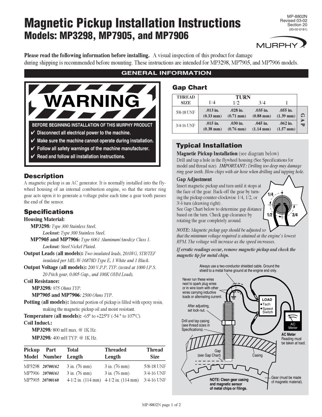
Magnetic Pickup Installation (see diagram below)
Drill and tap a hole in the flywheel housing (See Specifications for model and thread size). IMPORTANT: Drilling too deep may damage ring gear teeth. Blow chips with air hose when drilling and tapping hole.
Description
A magnetic pickup is an AC generator. It is normally installed into the fly- wheel housing of an internal combustion engine, so that the starter ring gear acts upon it to generate a voltage pulse each time a gear tooth passes the end of the sensor.
Specifications
Housing Material:
Gap Adjustment
Insert magnetic pickup and turn until it stops at the face of the gear.
See Gap Chart below to determine gap distance based on the turn. Check gap clearance by rotating the gear completely around.
1/4
1/2
3/4
MP3298: Type 300 Stainless Steel. Locknut: Type 300 Stainless Steel.
MP7905 and MP7906: Type 6061 Aluminum/Anodize Class 1. Locknut: Steel Nickel Plated.
Output Leads (all models): Two insulated leads, 20AWG, STR/TEF insulated per
Output Voltage (all models): 200 V.P.P. TYP. (tested at 1000 I.P.S. 20 Pitch gear, 0.005 Gap., and 100K OHM Load).
NOTE: Magnetic pickup gap should be adjusted so
that the minimum voltage required is attained at the engine’s lowest RPM. The voltage will increase as the speed increases.
If erratic readings occur, remove magnetic pickup and check the magnetic tip for metal chips.
Always use a
Coil Resistance:
MP3298: 975 Ohms TYP.
MP7905 and MP7906: 2500 Ohms TYP.
Potting (all models): Internal portion of pickup is filled with epoxy resin, making the magnetic pickup oil and moist resistant.
Temperature (all models):
Coil Induct.:
MP3298: 800 mH max, @ 1K Hz.
MP3298: 400 mH TYP. @ 1K Hz.
Pickup | Part | Total | Threaded | Thread |
Model | Number | Length | Length | Size |
|
|
|
|
|
MP3298 | 20700162 | 3 in. (76 mm) | 3 in. (76 mm) | |
MP7906 | 20700161 | 3 in. (76 mm) | 3 in. (76 mm) | |
MP7905 | 20700160 |
|
Never run these wires next to spark plug wires or in wire loom with other wires carrying inductive ![]() loads or alternating current.
loads or alternating current. ![]()
After adjusting, set
Drill and tap casing ![]() (see thread sizes in
(see thread sizes in ![]() Specifications).
Specifications).![]()
Gap
(see Gap Chart)
NOTE: Clean gear casing and magnetic sensor
of metal chips or filings.
LOAD
![]() Tach
Tach
![]() Speed
Speed
Switch
AC
Meter
AC Meter Reading must be taken at load.
Casing
![]() Gear (must be made of magnetic material).
Gear (must be made of magnetic material).
