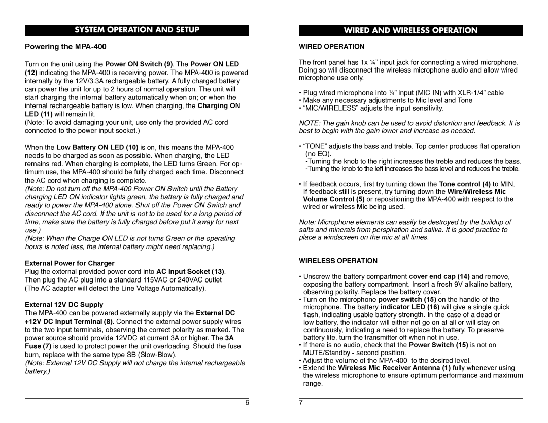
MPA-400 specifications
The Nady Systems MPA-400 is a versatile and powerful multi-channel amplifier designed for a wide range of applications in both live sound and installation scenarios. With its robust construction and innovative technology, the MPA-400 meets the demands of professional users seeking reliable performance and audio quality.One of the standout features of the MPA-400 is its four-channel design, allowing it to drive multiple speaker systems simultaneously. Each channel is independently adjustable, which provides users with the flexibility to tailor the output to suit various speakers and acoustic environments. The amplifier delivers a total output power of 400 watts, ensuring ample headroom for dynamic performances and events.
The MPA-400 incorporates advanced cooling technology, including internal fans that maintain optimal operating temperatures. This feature not only extends the lifespan of the unit but also ensures consistent performance during extended use. The weighted internal components are designed to minimize noise interference, contributing to the unit’s clean and clear audio output.
In terms of connectivity, the MPA-400 offers a comprehensive array of options. It includes balanced XLR inputs for professional-grade microphones and instruments, as well as RCA inputs for connecting consumer audio devices. The outputs provide compatibility with a range of speaker configurations, making it suitable for both passive and active monitoring systems.
The amplifier is engineered with a built-in limiter, which prevents peak overload while maintaining signal integrity. This safeguard is especially beneficial in live sound applications, where sudden volume spikes can lead to distortion or speaker damage. Additionally, the unit features LED indicators for signal presence and clipping, allowing users to monitor performance at a glance.
Portability is another significant advantage of the MPA-400. Its compact chassis and lightweight design enable easy transportation, making it an ideal choice for mobile DJs, bands, and sound reinforcement professionals. The rugged construction ensures it can withstand the rigors of frequent travel and setup.
Overall, the Nady Systems MPA-400 stands out in the crowded field of audio amplifiers thanks to its power, flexibility, and reliability. Whether for live performances, recording sessions, or public address use, the MPA-400 provides an exceptional solution for elevating sound quality and delivering exceptional audio experiences. Its combination of features and technologies makes it a valuable asset for any audio professional.

