PEQ-5B specifications
Nady Systems PEQ-5B is a versatile and high-performance equalizer designed specifically for professional audio applications. This unit is highly regarded for its rich feature set and exceptional audio quality, making it a favorite among musicians, sound engineers, and recording professionals.One of the standout features of the PEQ-5B is its five-band equalization. Each band operates independently, allowing for precise tuning of sound frequencies. The center frequencies are selectable and provide the user with a wide range of options to tailor the sound to specific needs. The bands include low (80Hz), low-mid (250Hz), mid (1KHz), high-mid (4KHz), and high (12KHz), enabling the user to enhance or reduce frequencies effectively based on the acoustic environment or individual sound preferences.
In terms of technology, the PEQ-5B employs a unique analog circuit design, which contributes to its warm and musical sound quality. This design helps maintain the integrity of the audio signal, reducing unwanted artifacts and preserving the original character of the sound source. The equalizer also features a low-cut filter, which is essential for removing unwanted low-frequency rumble or noise, further improving mix clarity.
Another characteristic worth noting is the PEQ-5B's robust construction. It features a rugged metal chassis designed to withstand the rigors of both studio and live environments. The intuitive layout of the control knobs allows for quick adjustments on the fly, making it user-friendly for performers and engineers alike. Additionally, the PEQ-5B is equipped with high-quality potentiometers, ensuring durability and reliability over time.
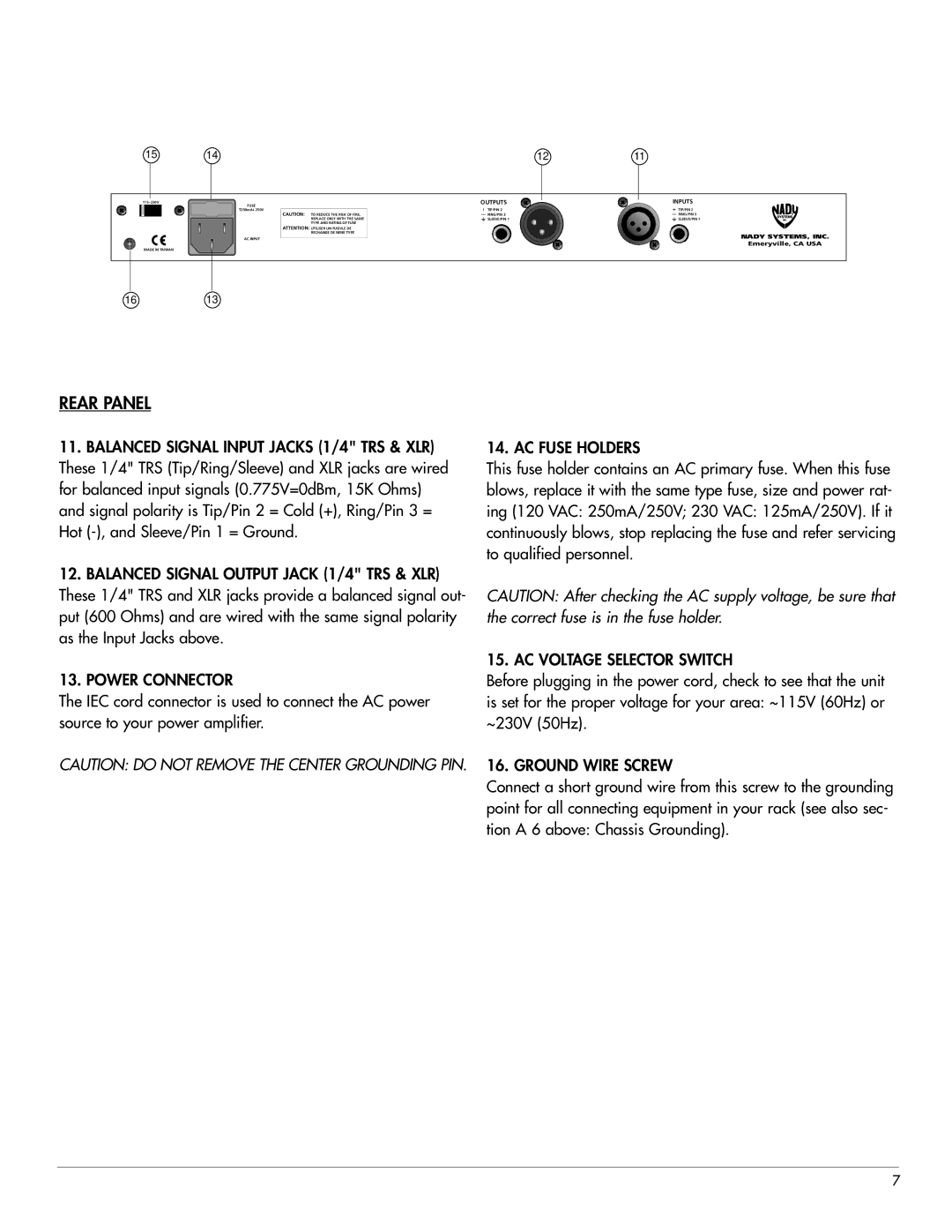
The PEQ-5B also includes a master output fader that lets users easily control the overall level after processing. This feature allows for quick adjustments without affecting individual band settings. The unit is designed for easy integration into any audio setup, making it compatible with a variety of mixing consoles, recording interfaces, and live sound systems.
In summary, Nady Systems PEQ-5B is a powerful equalizer with five bands of frequency control, intuitive analog technology, and durable construction. Its flexibility and user-friendly features make it an excellent choice for anyone looking to enhance their audio mixing and recording experience. Whether in a studio or on stage, the PEQ-5B remains a reliable tool for achieving superior sound quality.

