C O N T R O L S A N D C O N N E C T I O N S
(38) | (40) |
| (42) |
|
| |||||||
|
|
|
|
|
|
|
|
|
|
|
|
|
|
|
|
|
|
|
|
|
|
|
|
|
|
|
|
|
|
|
|
|
|
|
|
|
|
|
|
|
|
|
|
|
|
|
|
|
|
|
|
|
|
|
|
|
|
|
|
|
|
|
|
|
|
|
|
|
|
|
|
|
|
|
|
|
|
|
|
|
|
|
|
|
|
|
|
|
|
|
(39)(41)
BACK PANEL
and is pre the master AUX send control (30). When the AUX/MON switch (26) button is depressed, this output serves as the monitor output for the Right bus (see also Master Mix Function and Operation).
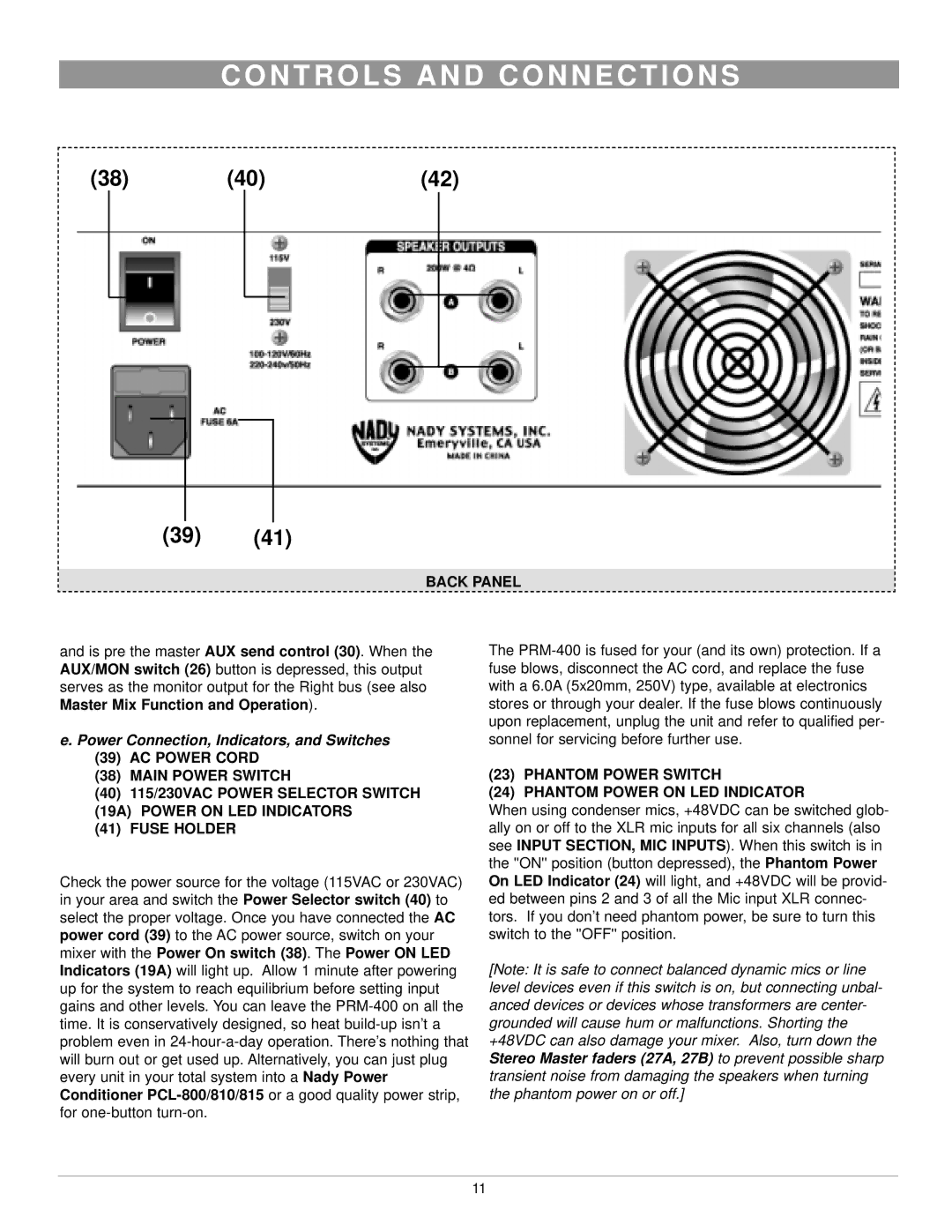
e. Power Connection, Indicators, and Switches
(39)AC POWER CORD
(38)MAIN POWER SWITCH
(40)115/230VAC POWER SELECTOR SWITCH (19A) POWER ON LED INDICATORS
(41)FUSE HOLDER
Check the power source for the voltage (115VAC or 230VAC) in your area and switch the Power Selector switch (40) to select the proper voltage. Once you have connected the AC power cord (39) to the AC power source, switch on your mixer with the Power On switch (38). The Power ON LED Indicators (19A) will light up. Allow 1 minute after powering up for the system to reach equilibrium before setting input gains and other levels. You can leave the
The
(23)PHANTOM POWER SWITCH
(24)PHANTOM POWER ON LED INDICATOR
When using condenser mics, +48VDC can be switched glob- ally on or off to the XLR mic inputs for all six channels (also see INPUT SECTION, MIC INPUTS). When this switch is in
the ''ON'' position (button depressed),Phantomt e Power On LED Indicator (24) will light, and +48VDC will be provid- ed between pins 2 and 3 of all the Mic input XLR connec- tors. If you don’t need phantom power, be sure to turn this switch to the ''OFF'' position.
[Note: It is safe to connect balanced dynamic mics or line level devices even if this switch is on, but connecting unbal- anced devices or devices whose transformers are center- grounded will cause hum or malfunctions. Shorting the +48VDC can also damage your mixer. Also, turn down the Stereo Master faders (27A, 27B) to prevent possible sharp transient noise from damaging the speakers when turning the phantom power on or off.]
11