CONTROLS AND CONNECTIONS
(11) L AND R LED VU METER
This will display the relative output level of the Left and Right Main PWR AMPS MODE (25) in STEREO and BRIDGE MODE. It will also display the relative output level of the PWR AMPS MODE
(25)in the MAIN/MONITOR switch position .
(12) L AND R MASTER
These controls the final level of the Left and Right Master Channel bus.
•They set the amount of the MASTER LEFT/RIGHT signal sent to the internal left/right power amplifier or the external power amplifier connected to the MIX OUT (36) jacks.
•The LEFT MASTER sets the level of the signal sent to the internal power amplifiers when the PWR AMP MODE (25)
selector is in the BRIDGE position.
(13) METER MODE
The METER MODE switch displays L/R BUS signals to power amps when in the L/R position.
When in the MAIN/MONITOR position, the Left VU Meter displays Main bus signal and the Right VU Meter displays Monitor bus signals to the power amps.
When in BRIDGE MODE, switch the METER MODE (13) to L/R position and Left VU Meter displays signal to the power amp.
3.DIGITAL EFFECT SECTION
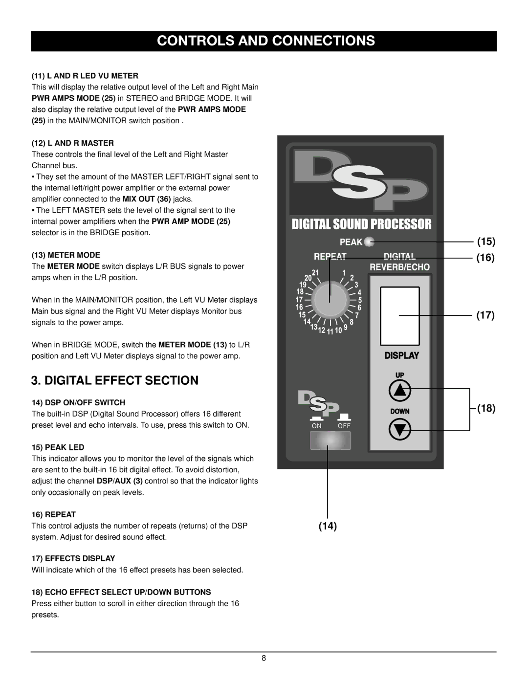
14)DSP ON/OFF SWITCH
The
15) PEAK LED
This indicator allows you to monitor the level of the signals which are sent to the
16) REPEAT
This control adjusts the number of repeats (returns) of the DSP system. Adjust for desired sound effect.
17) EFFECTS DISPLAY
Will indicate which of the 16 effect presets has been selected.
18) ECHO EFFECT SELECT UP/DOWN BUTTONS
Press either button to scroll in either direction through the 16 presets.
(14) |
(15)
(16)
(17)
(18)
8
