C O N T R O L S A N D C O N N E C T I O N S
1. MONO INPUT SECTION
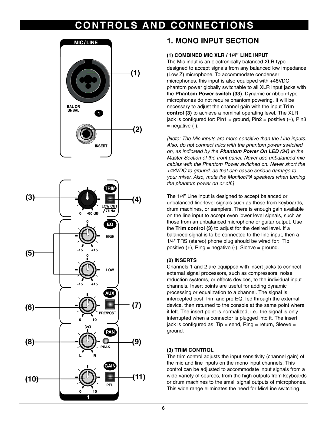
(1) COMBINED MIC XLR / 1/4” LINE INPUT
The Mic input is an electronically balanced XLR type designed to accept signals from any balanced low impedance
(1) (Low Z) microphone. To accommodate condenser microphones, this input is also equipped with +48VDC phantom power globally switchable to all XLR input jacks with the Phantom Power switch (33). Dynamic or
(3)
(2)
= negative
[Note: The Mic inputs are more sensitive than the Line inputs. Also, do not connect mics with the phantom power switched on, as indicated by the Phantom Power On LED (34) in the Master Section of the front panel. Never use unbalanced mic cables with the Phantom Power switched on. Never short the +48VDC to ground, as that can cause serious damage to your mixer. Also, mute the Monitor/PA speakers when turning the phantom power on or off.]
The 1/4” Line input is designed to accept balanced or
(5)
(6)
(8)
(10)
(4) unbalanced
(2) INSERTS
Channels 1 and 2 are equipped with insert jacks to connect external signal processors, such as compressors, noise reduction systems, or effects devices, to the individual input channels. Insert points are useful for adding dynamic processing or equalization to a channel. The signal is intercepted post Trim and pre EQ, fed through the external
(7) device, then returned to the console at the same point where it left. The insert point is normalized, i.e., the signal is only interrupted when a connector is plugged into it. The insert jack is configured as: Tip = send, Ring = return, Sleeve = ground.
(9)
(3) TRIM CONTROL
The trim control adjusts the input sensitivity (channel gain) of the mic and line inputs on the mono input channels. This control can be adjusted to accommodate input signals from a
(11) wide variety of sources, from the high outputs from keyboards or drum machines to the small signal outputs of microphones. This wide range eliminates the need for Mic/Line switching.
6