Connect a Matched Pair of
2 POE101 Adapters
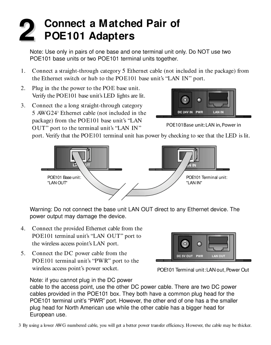
Note: Use only in pairs of one base and one terminal unit only. Do NOT use two POE101 base units or two POE101 terminal units together.
1.Connect a
2.Plug in the the power to the POE base unit.
Verify the POE101 base unit’s LED lights are lit.
3. Connect the a long
5 AWG243 Ethernet cable (not included in the |
|
|
|
|
|
|
|
|
|
|
|
|
|
|
|
|
|
|
|
|
|
|
|
|
|
|
|
|
|
|
|
|
|
|
|
|
|
| |
|
|
|
|
|
|
|
|
|
|
|
|
|
|
|
|
|
|
| |
package) from the POE101 base unit’s “LAN |
|
|
|
|
|
|
|
|
|
|
|
|
|
|
|
|
|
|
|
|
| POE101Base unit: LAN in, Power in | |||||||||||||||||
OUT” port to the terminal unit’s “LAN IN” |
|
| |||||||||||||||||
|
|
|
|
|
|
|
|
|
|
|
|
|
|
|
|
|
|
| |
port. Verify that the POE101 terminal unit has power by checking to see that the LED is lit.
LAN OUT | LAN IN |
POE101 Base unit: | POE101 Terminal unit: |
"LAN OUT" | "LAN IN" |
Warning: Do not connect the base unit LAN OUT direct to any Ethernet device. The power output may damage the device.
4.Connect the provided Ethernet cable from the POE101 terminal unit’s “LAN OUT” port to the wireless access point’s LAN port.
5.Connect the DC power cable from the POE101 terminal unit’s “PWR” port to the wireless access point’s power socket.
DC 5V OUT PWR | LAN OUT |
POE101 Terminal unit: LAN out, Power Out
Note: if you cannot plug in the DC power
cable to the access point, use the other DC power cable. There are two DC power cables provided in the POE101 box. They both have a common plug head for the POE101 terminal unit’s “PWR” port. However, the other end of one has a the smaller plug head for North American use while the other cable has a bigger head for European use.
3 By using a lower AWG numbered cable, you will get a better power transfer efficiency. However, the cable may be thicker.
