USING THE A-20 CONTROL FUNCTIONS:
The A-20 controls are designed for utility and repeatability under varying conditions. You should find the effects of the controls sonically subtle, with little impact on the basic character and accuracy of the speaker. We encourage experimentation to fine tune the system to the requirements of your particular installation.
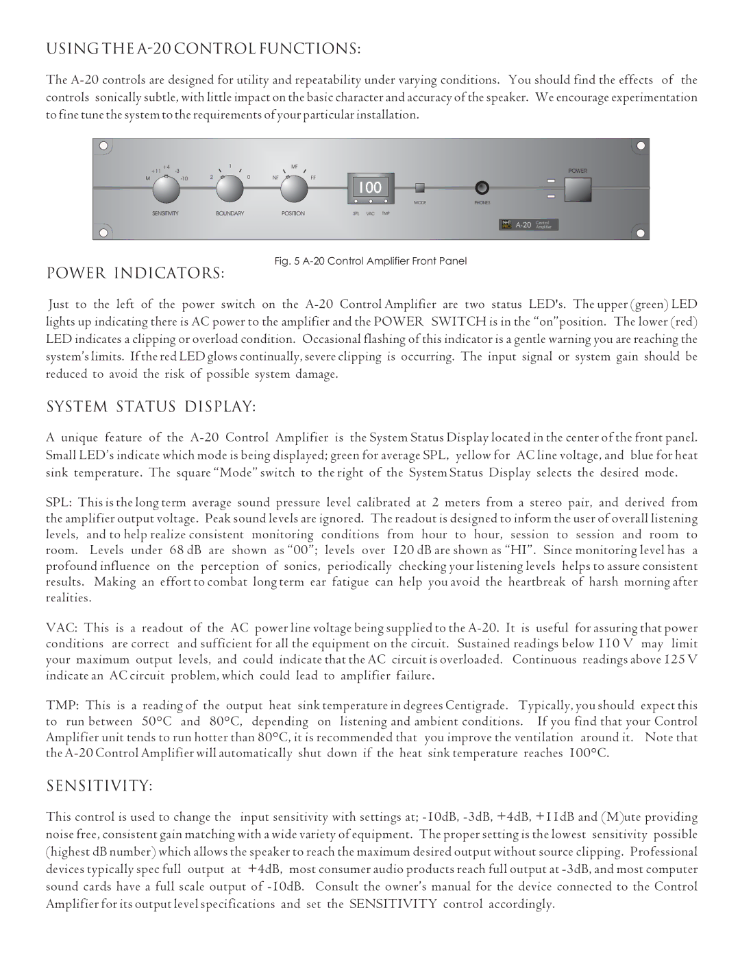
Fig. 5 A-20 Control Amplifier Front Panel
POWER INDICATORS:
Just to the left of the power switch on the A-20 Control Amplifier are two status LED's. The upper (green) LED lights up indicating there is AC power to the amplifier and the POWER SWITCH is in the “on”position. The lower (red) LED indicates a clipping or overload condition. Occasional flashing of this indicator is a gentle warning you are reaching the system’s limits. If the red LED glows continually, severe clipping is occurring. The input signal or system gain should be reduced to avoid the risk of possible system damage.
SYSTEM STATUS DISPLAY:
Aunique feature of the A-20 Control Amplifier is the System Status Display located in the center of the front panel. Small LED’s indicate which mode is being displayed; green for average SPL, yellow for AC line voltage, and blue for heat sink temperature. The square “Mode” switch to the right of the System Status Display selects the desired mode.
SPL: This is the long term average sound pressure level calibrated at 2 meters from a stereo pair, and derived from the amplifier output voltage. Peak sound levels are ignored. The readout is designed to inform the user of overall listening levels, and to help realize consistent monitoring conditions from hour to hour, session to session and room to room. Levels under 68 dB are shown as “00”; levels over 120 dB are shown as “HI”. Since monitoring level has a profound influence on the perception of sonics, periodically checking your listening levels helps to assure consistent results. Making an effort to combat long term ear fatigue can help you avoid the heartbreak of harsh morning after realities.
VAC: This is a readout of the AC power line voltage being supplied to the A-20. It is useful for assuring that power conditions are correct and sufficient for all the equipment on the circuit. Sustained readings below 110 V may limit your maximum output levels, and could indicate that the AC circuit is overloaded. Continuous readings above 125 V indicate an AC circuit problem, which could lead to amplifier failure.
TMP: This is a reading of the output heat sink temperature in degrees Centigrade. Typically, you should expect this to run between 50°C and 80°C, depending on listening and ambient conditions. If you find that your Control Amplifier unit tends to run hotter than 80°C, it is recommended that you improve the ventilation around it. Note that the A-20 Control Amplifier will automatically shut down if the heat sink temperature reaches 100°C.
SENSITIVITY:
This control is used to change the input sensitivity with settings at; -10dB, -3dB, +4dB, +11dB and (M)ute providing noise free, consistent gain matching with a wide variety of equipment. The proper setting is the lowest sensitivity possible (highest dB number) which allows the speaker to reach the maximum desired output without source clipping. Professional devices typically spec full output at +4dB, most consumer audio products reach full output at -3dB, and most computer sound cards have a full scale output of -10dB. Consult the owner’s manual for the device connected to the Control Amplifier for its output level specifications and set the SENSITIVITY control accordingly.