
Powered Subwoofers specifications
NHT (New Technology HiFi) powered subwoofers are renowned for their ability to provide deep, rich bass that complements any audio setup. As part of a complete home theater or music system, NHT subwoofers are designed to deliver precise sound reproduction with minimal distortion, enhancing overall listening experiences.One of the notable features of NHT powered subwoofers is their built-in amplification. Unlike passive subwoofers that require an external amplifier, NHT subwoofers come equipped with high-quality, integrated amplifiers that are specifically tuned to match the driver components. This ensures optimal performance and efficient power usage, eliminating the need for additional equipment and simplifying setup.
NHT utilizes advanced driver technology in its subwoofers. The proprietary woofers are engineered for exceptional linearity and dynamic range, providing deep bass frequencies while remaining clear and undistorted even at higher volumes. This attention to detail in driver design allows NHT subwoofers to reproduce low-end frequencies with incredible accuracy, making them ideal for both music and cinematic soundtracks.
Another critical aspect of NHT powered subwoofers is their versatility in adjusting performance to fit individual preferences and room acoustics. Many models feature adjustable volume controls, phase controls, and low-pass filters. This allows users to customize the sound output to match the characteristics of their listening environment, whether it’s a small room or a larger home theater setup.
NHT subwoofers are also designed with aesthetic considerations in mind. They typically feature sleek, modern finishes that integrate seamlessly into various home decor styles. This design philosophy ensures that consumers do not have to compromise on aesthetics while enjoying high-quality audio performance.
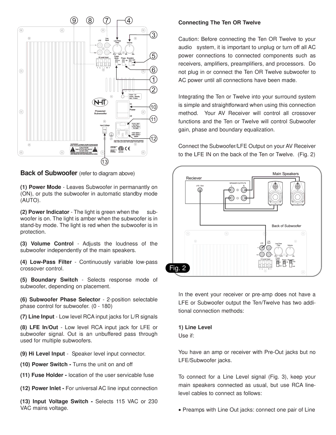
Connectivity options are extensive in NHT powered subwoofers, accommodating various setups. They often include both line-level RCA inputs for traditional audio sources and high-level speaker inputs for connection to home theater receivers. This flexibility enhances their compatibility with a range of audio components.
Overall, NHT powered subwoofers embody a blend of innovative technology, user-friendly features, and aesthetic appeal. They offer music and movie enthusiasts the powerful bass response needed for immersive audio experiences, making them a solid choice for anyone looking to enhance their sound systems with superior low-frequency performance. With their emphasis on quality and performance, NHT subwoofers continue to be a popular selection among audiophiles and home theater enthusiasts alike.