Before starting the installation, please observe the following precautions:
• Turn off all system power before | • Make sure hands are clean before |
making any connections | installation |
• Always wear protective eyewear | • Wear gloves when working with |
when using tools | fiberglass insulation |
RUNNING WIRES IN WALLS OR CEILINGS | |
When running loudspeaker wire inside walls or ceilings, use special jacketed cable (a minimum of 18 to 16-gauge two-conductor CL-2 or CL-3 rated loudspeaker wire) to protect the wire and for fire prevention. In some areas, conduit is also required. For a trouble-free installation, low-voltage wire such as loudspeaker wire must be run in accordance with the National Electrical Code and any applicable provisions of the local building code. If you are unsure of the correct installation techniques, wire jacket, or type of conduit to use, consult a professional audio/video installer, building contractor, or the local building and inspection department.
SELECTING THE LOCATION FOR YOUR LOUDSPEAKERS
The CM700 series loudspeakers are designed to be installed in any standard ceiling. There are two considerations for placing the loudspeaker; ease of running the cable to the loudspeaker and coverage of the loudspeaker. The best stereo effect will be achieved if both the loudspeakers are at equal distance from the listener and closer together than the listener is from the loudspeakers. Avoid installing the loudspeakers near corners to prevent a “boomy” or diffracted sound. The CM700 series loudspeakers will cover an area of a circle with a 16-foot diameter when mounted at an 8-foot height. (See Figure 1)
EXISTING CONSTRUCTION INSTALLATION
IMPORTANT: BEFORE YOU CUT INTO ANY WALL, REVIEW THE PRIOR SECTION ON LOUDSPEAKER PLACEMENT WHEN SELECTING THE LOCATION FOR YOUR LOUDSPEAKERS.
1.When determining the location of the loudspeaker cutout, keep in mind that the mounting dogs will extend 3/4” beyond the cutout. Make sure that you do not place the edge of the cutout directly next to a ceiling joist. Locate the joists using a stud sensor or by hand knocking. Use the supplied cutout template (remove the largest perforated circle and use cardboard square with hole as the template) to determine how large of a hole you will need to cut. These templates are packed with your loudspeakers between the styrofoam packing and the ends of the box.
2.Once you have determined a possible position for the cutout, drill a 1/8” pilot hole just barely through the ceiling (1/2” to 5/8” deep in most homes) in the center of your proposed loudspeaker location.
BE VERY CAREFUL NOT TO DRILL THROUGH EXISTING WIRES, PIPES, OR STRUCTURE. IF YOU FEEL ANY EXTRA RESISTANCE AS YOU ARE DRILLING, STOP.
The optional CM700 BKT can be used with the CM710, CM730, CM750 or CM760 loudspeakers. The hole saving bracket enables a faster and cleaner final installation of the loudspeaker. It forces the drywall installer to cut out the loudspeaker hole for you and provides wire ties for the loudspeaker wire, reducing the risks of accidental loss or movement of the wire. In addition, it enables you to align your loudspeakers with other ceiling fixtures with great accuracy since you can really see exactly where the loudspeaker will be. To install the bracket, first pivot the long wing out until it stops, which will be in straight line with the short wing. The wings and brackets have centering lines to simplify placement of the loudspeakers. Screw one side of the assembled bracket with wings to the joist using one of the supplied screws. Level the bracket. Screw the other side of the bracket/wing assembly to the joist. Two screws on each side make for a very secure installation. Secure the wire to the bracket using bracket’s wire tie tab. The drywall installers will cut the drywall to the exact size of the bracket. (See Figure 2)
CONCEALING LOUDSPEAKER WIRE FOR A FUTURE INSTALLATION
Attach the loudspeaker wire in a loop between the ceiling joists and carefully mark the exact location of the wire on a set of plans. Ask the general contractor to inform the drywall installers that the loudspeaker wire loops are concealed for future installations.
UNPACKING AND FINAL INSTALLATION
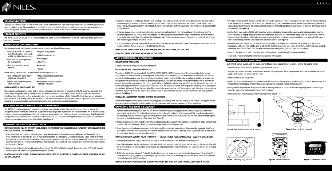
1.Remove the top piece of stryofoam from the box. You will find two loudspeakers bagged in a lower portion of packing. Remove the loudspeaker from the bag. The metal grille is installed on the loudspeaker and will need to be removed. This is easily done by rotating the mounting ‘dogs’ out with your fingers and pulling them towards the front of the loudspeaker. This will push the screw heads against the inside of the grille to work it out of the baffle. (See Figure 3)
2.At each loudspeaker location, route the wire to the input connectors, then separate the loudspeaker wire so that at least 2 inches of each conductor are free. Strip away 1/4 inch of insulation from each individual loudspeaker wire.
3.Press down each spring-loaded connector one at a time, insert the appropriate conductor and then release the connector. Check to be sure that the connector is making contact with stripped wire and not the wire jacket. Gently tug on the loudspeaker wire to make sure it is held in place. If not, repeat this procedure until it is.
IMPORTANT: OBSERVE CORRECT POLARITY: POSITIVE (+) GOES TO THE RED POST AND NEGATIVE (–) GOES TO THE BLACK POST.
4.Rotate dogs back to their original positions so that they do not protrude out from the diameter of the loudspeaker.
5.Insert the loudspeaker into the hole by carefully holding it with both hands and angling it slowly into the hole until the frame is flush with the ceiling. Holding it in place carefully with one hand, (do not push against the woofer or tweeter) use a cordless drill to begin mounting the loudspeaker.
6.Tighten the four screws using a #2 Phillips bit. Use low torque and low speed or you may damage the loudspeaker. This should pull the frame and mounting dog together (sandwiching the drywall) so that the frame is absolutely flush with the wall surface. There should be no gaps between the wall and the frame.
IMPORTANT: DO NOT OVER TIGHTEN THE SCREWS! OVER TIGHTENING THEM MAY MAKE THE GRILLE DIFFICULT TO INSTALL