|
|
|
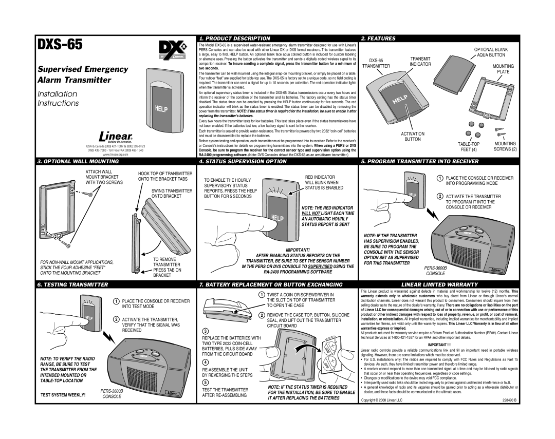
| 1. PRODUCT DESCRIPTION | 2. FEATURES |
|
| ||
|
|
| The Model |
|
| OPTIONAL BLANK | |||
|
|
| PERS Consoles and can also be used with other Linear DX or DXS format receivers. This transmitter features |
|
| ||||
|
|
| BY | a large, easy to fi nd, HELP button. An optional blank face aqua colored button is included for custom labeling |
|
| AQUA BUTTON | ||
|
|
|
| or alternate uses. Pressing the button activates the transmitter and sends a digitally coded wireless signal to its |
| TRANSMIT |
| ||
|
|
|
| companion receiver. To insure sending a complete signal, press the transmitter button for a minimum of |
| INDICATOR |
| ||
Supervised Emergency |
|
|
| TRANSMITTER | MOUNTING | ||||
|
| two seconds. |
|
|
| ||||
|
|
|
|
|
| PLATE | |||
|
|
|
|
|
|
|
|
| |
Alarm Transmitter |
|
| The transmitter can be wall mounted using the integral |
|
|
|
| ||
|
| required. The transmitter can send a signal for up to 10 seconds per activation. The red operation indicator lights |
|
|
|
| |||
|
|
|
| Four rubber “feet” are supplied for |
|
|
|
| |
Installation |
|
|
| when the transmitter is activated. |
|
|
|
|
|
|
|
| An optional supervisory status timer is included in the |
|
|
|
| ||
|
|
|
|
|
|
|
| ||
Instructions |
|
|
| inform the receiver of the condition of the transmitter and its batteries. The factory setting has the status timer |
|
|
|
| |
|
|
| disabled. The status timer can be enabled by pressing the HELP button continuously for fi ve seconds. The red |
|
|
|
| ||
|
|
|
|
|
|
|
| ||
|
|
|
| operation indicator will blink as the status timer is enabled. The status timer can be disabled by removing the |
|
|
|
| |
|
|
|
| power from the transmitter. NOTE: If the status timer is required for the installation, be sure to enable it after |
|
|
|
| |
|
|
|
| replacing the transmitter’s batteries. |
|
|
|
|
|
|
|
|
| Every two hours the transmitter tests for low batteries. This test takes place even if the status transmissions have |
|
|
|
| |
|
|
|
| not been enabled. If the batteries test low, a low battery signal is sent to the receiver. |
|
|
|
| |
|
|
|
| Each transmitter is sealed to provide |
|
| ACTIVATION |
| |
|
|
|
| and must be disassembled to replace the batteries. |
|
|
| ||
|
|
|
|
|
| BUTTON |
| ||
|
|
|
| Before system testing and operation, each transmitter must be programmed into its receiver. Refer to the receiver’s |
|
| MOUNTING | ||
|
|
|
|
|
|
| |||
| USA & Canada (800) |
| or Console’s instructions for details on programming transmitters into the system. When using a PERS or DVS |
|
| ||||
|
|
|
| FEET (4) | SCREWS (2) | ||||
| (760) |
| Console, be sure to program the receiver for the correct sensor type and supervision option using the |
|
| ||||
| www.linearcorp.com |
|
|
|
|
|
| ||
3. OPTIONAL WALL MOUNTING |
|
| 4. STATUS SUPERVISION OPTION | 5. PROGRAM TRANSMITTER INTO RECEIVER |
| ||||
| ATTACH WALL | HOOK TOP OF TRANSMITTER |
|
|
|
|
|
| |
| MOUNT BRACKET |
| RED INDICATOR |
|
| 1 PLACE THE CONSOLE OR RECEIVER | |||
| ONTO THE BRACKET TABS | TO ENABLE THE HOURLY |
|
| |||||
| WITH TWO SCREWS | WILL BLINK WHEN |
|
| |||||
|
|
| SUPERVISORY STATUS |
|
| INTO PROGRAMMING MODE | |||
|
|
| SWING TRANSMITTER | STATUS IS ENABLED |
|
|
|
| |
|
|
| REPORTS, PRESS THE HELP |
|
|
|
| ||
|
|
|
|
|
| 2 ACTIVATE THE TRANSMITTER | |||
|
|
| ONTO BRACKET | BUTTON FOR 5 SECONDS |
|
|
| ||
|
|
|
|
|
|
|
| TO PROGRAM IT INTO THE | |
|
|
|
|
| NOTE: THE RED INDICATOR |
|
| CONSOLE OR RECEIVER |
|
|
|
|
|
| WILL NOT LIGHT EACH TIME |
|
|
|
|
|
|
|
|
| AN AUTOMATIC HOURLY |
|
|
|
|
|
|
|
|
| STATUS REPORT IS SENT |
|
|
|
|
|
|
|
|
|
|
| NOTE: IF THE TRANSMITTER |
| |
|
|
|
|
|
|
| HAS SUPERVISION ENABLED, |
| |
|
|
|
|
| IMPORTANT! |
| BE SURE TO PROGRAM THE |
| |
|
|
|
|
|
| CONSOLE WITH THE SENSOR |
| ||
|
|
|
| AFTER ENABLING STATUS REPORTS ON THE |
|
| |||
|
|
| TO REMOVE |
| OPTION SET AS SUPERVISED |
| |||
FOR |
| TRANSMITTER, BE SURE TO SET THE SENSOR NUMBER |
|
| |||||
|
| FOR THIS TRANSMITTER |
| ||||||
| TRANSMITTER |
|
| ||||||
| IN THE PERS OR DVS CONSOLE TO SUPERVISED USING THE |
|
| ||||||
STICK THE FOUR ADHESIVE "FEET" |
|
|
|
| |||||
| PRESS TAB ON |
|
|
| |||||
ONTO THE MOUNTING BRACKET |
|
|
|
| CONSOLE |
| |||
| BRACKET |
|
|
|
| ||||
|
|
|
|
|
|
|
|
| |
6. TESTING TRANSMITTER |
|
| 7. BATTERY REPLACEMENT OR BUTTON EXCHANGING |
|
| LINEAR LIMITED WARRANTY |
| ||
|
|
|
|
| 1 TWIST A COIN OR SCREWDRIVER IN | This Linear product is warranted against defects in material and workmanship for twelve (12) months. This | |||
|
|
|
|
| warranty extends only to wholesale customers who buy direct from Linear or through Linear’s normal | ||||
| 1 PLACE THE CONSOLE OR RECEIVER |
| THE SLOT ON TOP OF TRANSMITTER | distribution channels. Linear does not warrant this product to consumers. Consumers should inquire from their | |||||
| INTO TEST MODE |
| TO OPEN THE CASE | selling dealer as to the nature of the dealer’s warranty, if any. There are no obligations or liabilities on the part | |||||
|
|
|
|
|
| of Linear LLC for consequential damages arising out of or in connection with use or performance of this | |||
| 2 ACTIVATE THE TRANSMITTER, |
| 2 REMOVE THE CASE TOP, BUTTON, SILICONE | product or other indirect damages with respect to loss of property, revenue, or profit, or cost of removal, | |||||
|
| SEAL, AND LIFT OUT THE TRANSMITTER | installation, or reinstallation. All implied warranties, including implied warranties for merchantability and implied | ||||||
| VERIFY THAT THE SIGNAL WAS |
| CIRCUIT BOARD | warranties for fi tness, are valid only until the warranty expires. This Linear LLC Warranty is in lieu of all other | |||||
|
| warranties express or implied. |
| ||||||
| RECEIVED |
| 3 |
|
| ||||
|
|
| All products returned for warranty service require a Return Product Authorization Number (RPA#). Contact Linear | ||||||
|
|
|
| REPLACE THE BATTERIES WITH | Technical Services at |
| |||
|
|
|
| TWO TYPE 2032 |
|
|
| IMPORTANT !!! |
|
|
|
|
| BATTERIES, PLUS SIDE AWAY |
| Linear radio controls provide a reliable communications link and fi ll an important need in portable wireless | |||
NOTE: TO VERIFY THE RADIO |
|
| FROM THE CIRCUIT BOARD |
| signaling. However, there are some limitations which must be observed. |
| |||
|
| 4 |
| • | For U.S. installations only: The radios are required to comply with FCC Rules and Regulations as Part 15 | ||||
RANGE, BE SURE TO TEST |
|
|
|
| devices. As such, they have limited transmitter power and therefore limited range. |
| |||
|
|
|
|
|
| ||||
THE TRANSMITTER FROM THE |
|
|
|
| • | A receiver cannot respond to more than one transmitted signal at a time and may be blocked by radio signals | |||
INTENDED MOUNTED OR |
|
| BY REVERSING THE STEPS |
|
| that occur on or near their operating frequencies, regardless of code settings. |
| ||
|
|
| • Changes or modifi cations to the device may void FCC compliance. |
| |||||
|
|
|
| 5 |
|
| |||
|
|
|
| • Infrequently used radio links should be tested regularly to protect against undetected interference or fault. | |||||
|
|
|
| NOTE: IF THE STATUS TIMER IS REQUIRED | |||||
|
|
| TEST THE TRANSMITTER | • | A general knowledge of radio and its vagaries should be gained prior to acting as a wholesale distributor or | ||||
TEST SYSTEM WEEKLY! |
|
| FOR THE INSTALLATION, BE SURE TO ENABLE |
| dealer, and these facts should be communicated to the ultimate users. |
| |||
CONSOLE |
|
| AFTER | IT AFTER REPLACING THE BATTERIES | Copyright © 2008 Linear LLC | 228490 B | |||
|
|
|
|
| |||||
|
|
|
|
|
| ||||