MODEL RSL-6 Remote Controlled Speaker Selection System (continued)

 APPLICATION NOTES


Connections | Impedance Matching |
have an external sensor in the same room as the
If your amplifier has both “A” and “B” speaker pair outputs connect the
Using the RSL-6 with Tube-Type Amplifiers
Virtually all tube amplifiers must be connected to a load at all times. If you are using the
Use the SPEAKER DIP switches on the rear panel of the
Interfacing with a Multi-Room Infrared Repeater System
If you are using a Niles IR repeater sys- tem to relay remote control commands you may connect the FLASHER OUTPUT or OPTION OUT of the repeater directly to the IR DATA IN on the rear of the
feedback by disabling the front panel IR sensor using the rear panel EYE DIP switch.
X-10 Interfacing
If you are using
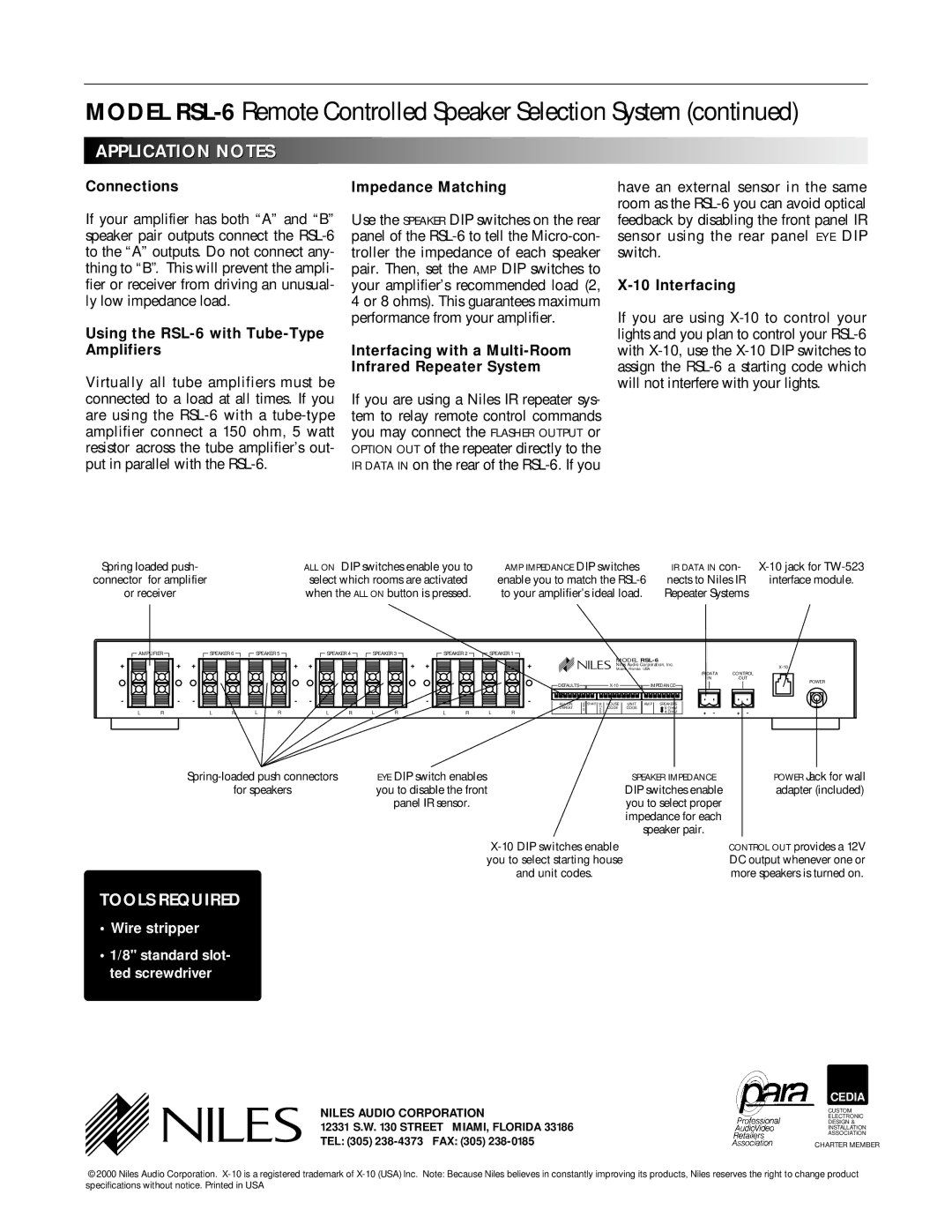
Spring loaded push- | ALL ON DIP switches enable you to |
connector for amplifier | select which rooms are activated |
or receiver | when the ALL ON button is pressed. |
AMP IMPEDANCE DIP switches | IR DATA IN con- | |
enable you to match the | nects to Niles IR | interface module. |
to your amplifier’s ideal load. | Repeater Systems |
|
AMPLIFIER |
| SPEAKER 6 | SPEAKER 5 | SPEAKER 4 | SPEAKER 3 |
| SPEAKER 2 | SPEAKER 1 | |||||||
+ | + | + |
|
|
| + | + |
|
|
| + | + |
|
| + |
- | - | - |
|
|
| - | - |
|
|
| - | - |
|
| - |
L | R |
| L | R | L | R | L | R | L | R |
| L | R | L | R |
| NILES | MODEL |
| Miami, Florida USA | |
|
| Niles Audio Corporation, Inc. |
![]() DEFAULTS
DEFAULTS ![]()
![]()
![]()
![]() IMPEDANCE
IMPEDANCE ![]()
|
|
|
|
|
|
|
|
|
|
|
|
|
|
|
|
|
|
|
|
|
|
|
|
|
|
|
|
|
|
|
|
|
|
|
|
|
|
|
|
|
|
|
|
|
|
|
|
|
|
|
|
| ALL ON | E | START | M | HOUSE |
| UNIT | AMP |
|
| SPEAKERS |
|
|
|
| ||||||||||||||||||||||||||||||||||
|
| DEFEAT | Y |
|
| O | CODE |
| CODE |
|
|
|
|
|
|
|
|
| 8 OHM | |||||||||||||||||||||||||||||||
|
| E |
|
| D |
|
|
|
|
|
|
|
|
|
| |||||||||||||||||||||||||||||||||||
|
|
|
|
|
|
|
|
|
|
|
|
|
|
|
| E |
|
|
|
|
|
|
|
|
|
|
|
|
|
|
|
|
|
|
|
|
|
| ➡4 OHM | |||||||||||
|
|
| |
IR DATA | CONTROL | ||
IN | OUT | ||
|
|
| POWER |
|
|
|
|
+ - | + - |
EYE DIP switch enables | SPEAKER IMPEDANCE | POWER Jack for wall | |
for speakers | you to disable the front | DIP switches enable | adapter (included) |
| panel IR sensor. | you to select proper |
|
|
| impedance for each |
|
|
| speaker pair. |
|
|
| CONTROL OUT provides a 12V | |
| you to select starting house |
| DC output whenever one or |
| and unit codes. |
| more speakers is turned on. |
TOOLS REQUIRED
•Wire stripper
•1/8" standard slot- ted screwdriver
| NILES AUDIO CORPORATION | CEDIA |
| CUSTOM | |
| ELECTRONIC | |
| 12331 S.W. 130 STREET MIAMI, FLORIDA 33186 | DESIGN & |
| INSTALLATION | |
| TEL: (305) | ASSOCIATION |
| CHARTER MEMBER | |
|
|
|
©2000 Niles Audio Corporation.
