INTRODUCTION
The MF Series of MicroFlashers are miniature panel-mount IR flashers. They are one of three elements needed to complete a remote control extender system:
•IR Main System Unit—Models MSU140, MSU250, MSU480 and MSU440Z.
•IR Sensors/Keypads—Models WS100, TS100, MS100, MS200, CS100, MVC100IR and the IntelliPad®.
•IR Flashers—Models MF1, MF1VF, MF2, MF2VF and the IRB1.
An IR sensor expansion hub, Model IRH610, is available to provide additional sensor inputs to your system.
When an IR remote sensor receives a command from a hand-held remote control, it sends a corresponding electronic signal through a wire to the main system unit. Here, the main system unit cleans and amplifies the electronic signal. Finally, the main system unit outputs the signal to the IR flasher which transmits the infrared command to the audio/video component you wish to control.
The MF MicroFlasher® sends the IR commands via flashes of infrared light in a precise pinpoint pattern from its single infrared LED. The output is extraordinarily accurate throughout a wide bandwidth. This allows the MF MicroFlashers to control most makes and models of IR controlled audio/video components.
The MF MicroFlashers are compatible with all Niles infrared extenders systems, IntelliControl® and MultiZone receivers and preamplifiers.
FEATURES & BENEFITS
•Miniature and discrete, the MF MicroFlashers mount directly to the IR remote sensor win- dow of your audio/video component without disfiguring the appearance of your equipment.
•The MF Series is completely transparent to IR commands. Although the flashers appear to block the IR remote sensor window of your audio/video component, you can still directly operate your equipment using a remote control.
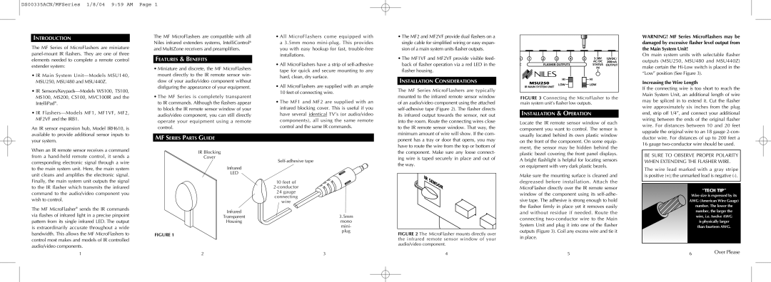
MF SERIES PARTS GUIDE
IR Blocking
Cover
Infrared
LED
Infrared
Transparent
Housing
FIGURE 1
•All MicroFlashers come equipped with a 3.5mm mono mini-plug. This provides you with easy hookup for fast, trouble-free installations.
•All MicroFlashers have a strip of self-adhesive tape for quick and secure mounting to any hard, clean, dry surface.
•All MicroFlashers are supplied with an ample 10 feet of connecting wire.
•The MF1 and MF2 are supplied with an infrared blocking cover. This is useful if you have several identical TV’s (or audio/video components), all using the same remote control and the same IR commands.
Self-adhesive tape
10 feet of
2-conductor
24gauge connecting
wire
3.5mm
mono mini- plug
•The MF2 and MF2VF provide dual flashers on a single cable for simplified wiring or easy expan- sion of a main system units flasher outputs.
•The MF1VF and MF2VF provide visible feed- back of flasher operation via a red LED in the flasher housing.
INSTALLATION CONSIDERATIONS
The MF Series MicroFlashers are typically mounted to the infrared remote sensor window of an audio/video component using the attached self-adhesive tape (Figure 2). The flasher directs its infrared output towards the sensor, not out into the room. Route the connecting wires close to the IR remote sensor window. That way, the minimum amount of wire will show. If the com- ponent has a tray or door that opens, you may have to route the wire from the top or bottom of the component. Make sure any loose connect- ing wire is taped securely in place and out of the way.
FIGURE 2 The MicroFlasher mounts directly over the infrared remote sensor window of your audio/video component.
FIGURE 3 Connecting the MicroFlasher to the main system unit’s flasher low outputs.
INSTALLATION & OPERATION
Locate the IR remote sensor window of each component you want to control. The sensor is usually located behind its own plastic window on the front of the component. On some equip- ment, the sensor may be hidden behind the plastic bezel covering the front panel displays. A bright flashlight is helpful for locating sensors on equipment with very dark plastic bezels.
Make sure the mounting surface is cleaned and degreased before installation. Attach the MicroFlasher directly over the IR remote sensor window of the component using its self-adhe- sive tape. The adhesive is strong enough to hold the flasher firmly in place yet it removes easily and without residue if needed. Route the connecting two-conductor wire to the Main System Unit and plug it into one of the flasher outputs (Figure 3). Coil any excess wire and tie it in place.
WARNING! MF Series MicroFlashers may be damaged by excessive flasher level output from the Main System Unit!
On main system units with selectable flasher outputs (MSU250, MSU480 and MSU440Z) make certain the Hi-Low switch is placed in the “Low” position (See Figure 3).
Increasing the Wire Length
If the connecting wire is too short to reach the Main System Unit, an additional length of wire may be spliced in to extend it. Cut the flasher wire approximately six inches from the plug end, strip off 1/4”, and connect your additional wiring between the ends of the original flasher wire. For distances between 10 and 20 feet upgrade the original wire to an 18 gauge 2-con- ductor wire. For distances of up to 200 feet a 16 gauge two-conductor wire should be used.
BE SURE TO OBSERVE PROPER POLARITY WHEN EXTENDING THE FLASHER WIRE.
The wire lead marked with a gray stripe is positive (+); the unmarked lead is negative (-).
“TECH TIP”
Wire size is expressed by its AWG (American Wire Gauge) number. The lower the number, the larger the
wire, i.e. twelve AWG
is physically larger than fourteen AWG.