Signal LED
These signal indicators light up when the output is more than 100mV.
5. Level Control | 5 |
These level controls are used to adjust the output signal level, you'd better adjust them properly to avoid any distortion.
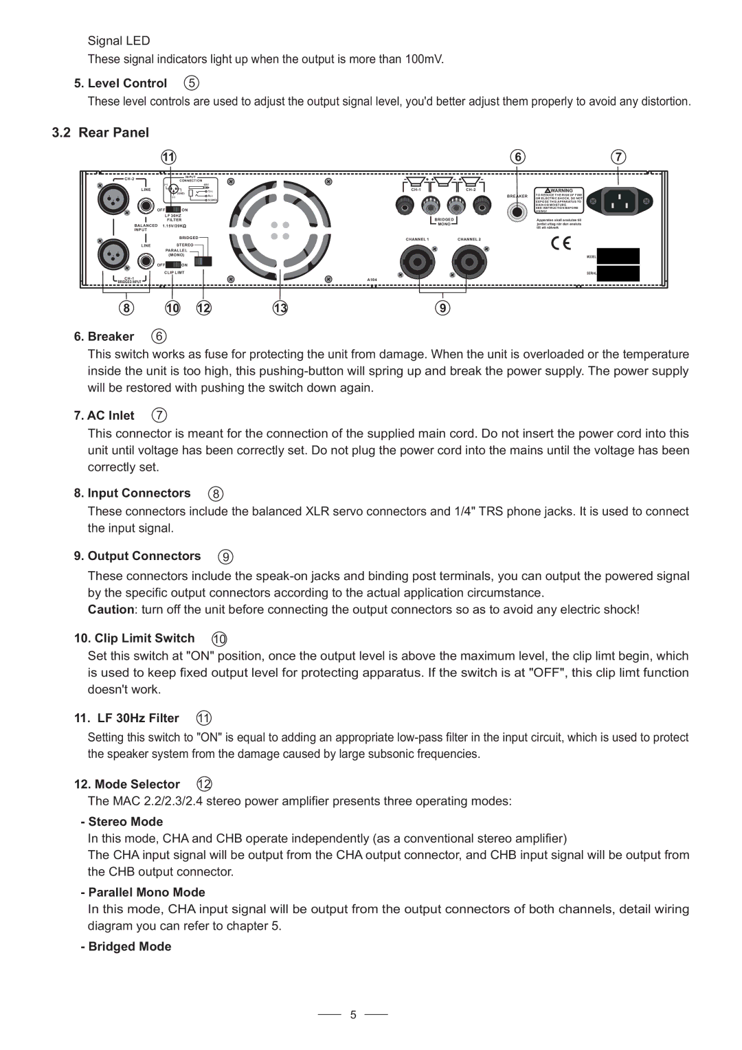
3.2 Rear Panel
11
|
| INPUT | |
|
| CONNECTION | |
| (+) | SRT | |
| LINE | 2 | 1 |
| 3 | T(+) | |
|
|
| (GND) |
2 | 1 | ||
| 3 |
| S(GND) |
| OFF |
| ON |
| LF 30HZ | ||
|
| FILTER | |
| BALANCED 1.15V/20K | ||
| INPUT |
|
|
|
|
| BRIDGED |
| LINE |
| STEREO |
2 | 1 | PARALLEL | |
| 3 | (MONO) | |
| OFF |
| ON |
| CLIP LIMT | ||
BRIDGED INPUT
| 6 | 7 |
WARNING | ||
| BREAKER | TO REDUCE THE RISK OF FIRE |
|
| OR ELECTRIC SHOCK, DO NOT |
|
| EXPOSE THIS APPARATUS TO |
|
| RAIN OR MOISTURE. |
|
| SEE INSTRUCTION BEFORE |
|
| USING! |
| BRIDGED | Apparaten skall anslutas till |
| MONO | jordat uttag nar den ansluts |
|
| till ett natverk |
CHANNEL 1 | CHANNEL 2 |
|
MODEL
SERIAL
A104
8 | 10 | 12 | 13 | 9 |
6. Breaker | 6 |
This switch works as fuse for protecting the unit from damage. When the unit is overloaded or the temperature inside the unit is too high, this
7. AC Inlet 7
This connector is meant for the connection of the supplied main cord. Do not insert the power cord into this unit until voltage has been correctly set. Do not plug the power cord into the mains until the voltage has been correctly set.
8. Input Connectors | 8 |
These connectors include the balanced XLR servo connectors and 1/4" TRS phone jacks. It is used to connect the input signal.
9. Output Connectors | 9 |
These connectors include the
Caution: turn off the unit before connecting the output connectors so as to avoid any electric shock!
10. Clip Limit Switch 10
Set this switch at "ON" position, once the output level is above the maximum level, the clip limt begin, which is used to keep fixed output level for protecting apparatus. If the switch is at "OFF", this clip limt function doesn't work.
11. LF 30Hz Filter 11
Setting this switch to "ON" is equal to adding an appropriate
12. Mode Selector 12
The MAC 2.2/2.3/2.4 stereo power amplifier presents three operating modes:
-Stereo Mode
In this mode, CHA and CHB operate independently (as a conventional stereo amplifier)
The CHA input signal will be output from the CHA output connector, and CHB input signal will be output from the CHB output connector.
-Parallel Mono Mode
In this mode, CHA input signal will be output from the output connectors of both channels, detail wiring diagram you can refer to chapter 5.
-Bridged Mode
5