INSTALLATION INSTRUCTIONS
READ & SAVE THESE INSTRUCTIONS!
INSTRUCTIONS D'INSTALLATION
LIRE ET CONSERVER CES INSTRUCTIONS!
Deluxe | BAIGNOIRE OU AU PLAFOND D'UNE CABINE DE DOUCHE. | |||
|
|
| IMPORTANT: NE PS INSTALLER | |
MODELS: 9093 SERIES |
| PRECAUTIONS POUR L'INSTALLATION | ||
1. | Pour obtenir les résultats prévus, observer toutes les | |||
IMPORTANT: DO NOT MOUNT OVER TUB OR IN SHOWER |
|
| recommandations de cette brouchure et tour les signes | |
STALL ENCLOSURE. | 2. | figurant sur l'appareil. | ||
INSTALLATION PRECAUTIONS | Vérifier toutes les fonctions de l'appareil lorsque l'installation | |||
|
| est terminée. | ||
| 3. | Le boîtier de l'appareil de chauffage doivent être reliés à la | ||
NOTE: Cutout dimensions 131⁄4" diameter. | ||||
|
| terre, et le câblage doit respecter tous | ||
1. Observe all requirements in these instructions and all markings | 4. | les règlements locaux. | ||
appearing on the unit. | Le rebord du boîtier d'encastrement DOIT venir à ras du plafond | |||
2. Check all operations of the unit after installation has been | 5. | fini pour un fonctionnement absolument sûr et adéquat. | ||
completed. | Si l'on vaporise les murs ou le plafond de plâtre ou de peinture, | |||
3. The housing must be grounded and the installed wiring must | 6. | l'intérieur du boîtier doit être protégé. | ||
comply with all local electrical codes. | L'interrupteur (fourni) doit être utilisé et relié en suivant le schéma | |||
4. The flange of the |
|
| de câblage. | |
the finished plaster or drywall surface to assure proper |
|
| • Peut être installé dans des plafonds inclinés avec une pente | |
and safe operation. |
|
| allant jusqu’à 12/12. | |
5. If plaster material, paint base, or paint is sprayed on the walls or |
|
| • La gaine doit pointer vers le haut. | |
ceiling, the inside of the housing must be masked off to prevent |
| PREPARATION DE L'INSTALLATION | ||
this material from entering the housing. |
| |||
6. The switch (furnished) should be used and wired in accordance |
|
|
| |
1. | Retirer l'ensemble complet de l'emballage. Desserrer les vis retenant | |||
with the wiring diagram. | ||||
|
| la grille et l'enlever. | ||
• For installation in sloped ceilings up to 12/12 pitch. |
|
| ||
2. | Desserrer les vis de montage du | |||
• Ductwork must point up. | ||||
|
| d'encastrement. | ||
| 3. | |||
INSTALLATION PREPARATION | Enlever l'adhésif du registre antirefoulement et s'assurer que rien | |||
|
| n'empêche l'ouverture et la fermeture de | ||
1. Remove complete assembly from carton. Loosen screws holding |
| MONTAGE AUX SOLIVES | ||
grille and remove the grille. |
| Voir la Figure 1. | ||
2. Loosen power unit mounting screws and remove power unit from |
| |||
| 1. Insérer la barre de suspension dans la patte de montage opposée | |||
|
| |||
|
| à l'ouverture d'évacuation, et monteur le boîtier d'encastrement aux | ||
3. Remove tape from back draft damper and be certain the damper |
|
| ||
|
| solives à l'emplacement désiré. | ||
opens and closes freely. | 2. | |||
Installer les pattes de montage dans les fentes du boîtier et l'ajuster | ||||
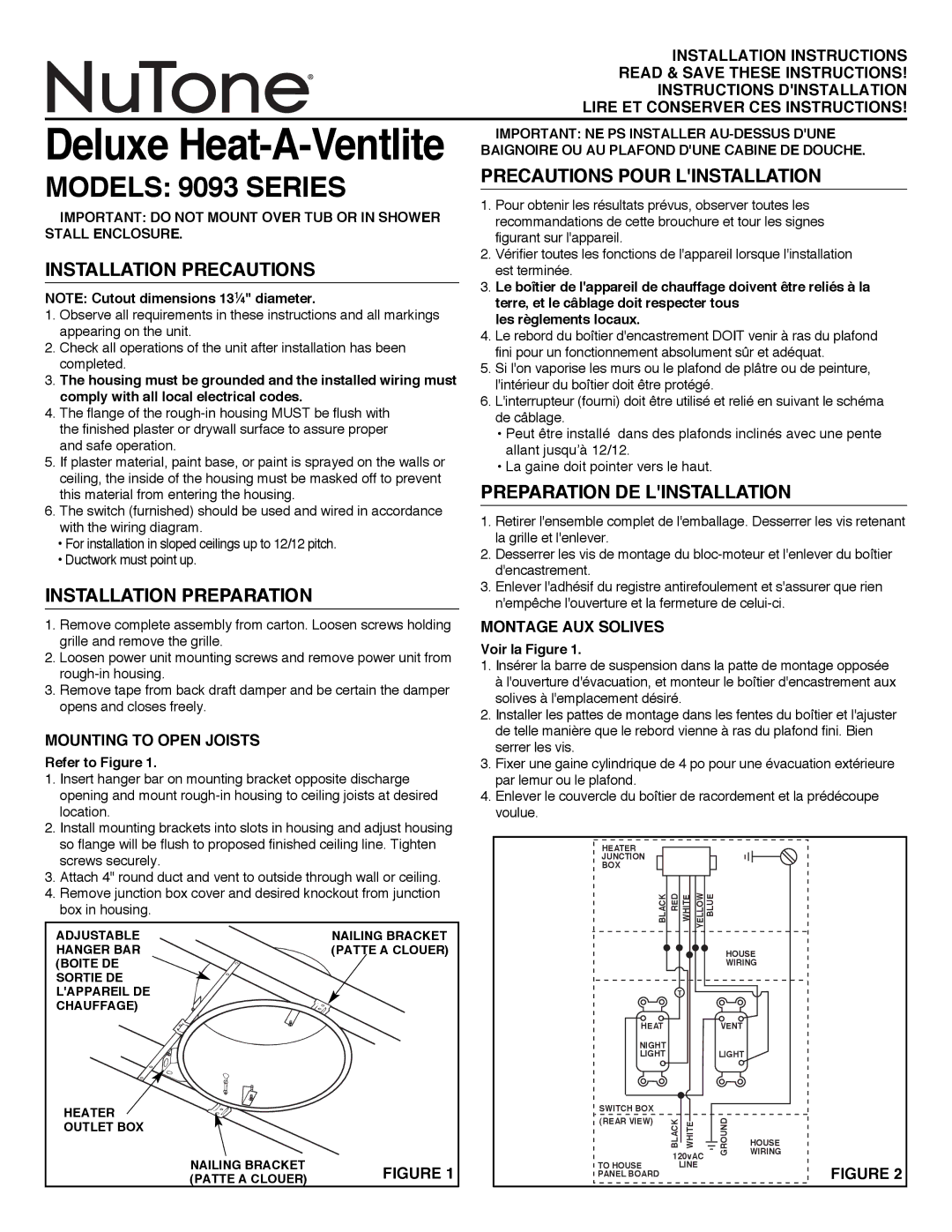
MOUNTING TO OPEN JOISTS |
|
| de telle manière que le rebord vienne à ras du plafond fini. Bien | |
3. | serrer les vis. | |||
Refer to Figure 1. | Fixer une gaine cylindrique de 4 po pour une évacuation extérieure | |||
1. Insert hanger bar on mounting bracket opposite discharge | 4. | par lemur ou le plafond. | ||
opening and mount | Enlever le couvercle du boîtier de racordement et la prédécoupe | |||
location. |
|
| voulue. | |
2. Install mounting brackets into slots in housing and adjust housing |
|
|
|
|
| |
so flange will be flush to proposed finished ceiling line. Tighten | HEATER |
|
|
|
| |
screws securely. |
| JUNCTION |
|
|
|
|
| BOX |
|
|
|
| |
3. Attach 4" round duct and vent to outside through wall or ceiling. |
|
|
|
|
| |
4. Remove junction box cover and desired knockout from junction | BLACK | RED | WHITE YELLOW | BLUE |
| |
box in housing. |
|
| ||||
|
|
|
|
|
| |
ADJUSTABLE | NAILING BRACKET |
|
|
|
|
|
HANGER BAR | (PATTE A CLOUER) |
|
|
| HOUSE | |
(BOITE DE |
|
|
|
| WIRING | |
SORTIE DE |
|
|
|
|
|
|
L'APPAREIL DE |
|
| T |
|
| |
CHAUFFAGE) |
|
|
|
|
|
|
|
| HEAT |
|
| VENT |
|
|
| NIGHT |
|
| LIGHT |
|
|
| LIGHT |
|
|
| |
HEATER |
| SWITCH BOX |
|
|
|
|
| (REAR VIEW) | BLACK |
| GROUND |
| |
OUTLET BOX |
| WHITE | WIRING | |||
|
| |||||
|
|
|
|
| HOUSE | |
|
|
| 120vAC |
| ||
NAILING BRACKET |
| TO HOUSE |
|
| ||
FIGURE 1 |
| LINE |
| FIGURE 2 | ||
(PATTE A CLOUER) | PANEL BOARD |
|
|
| ||
|
|
|
|
|
| |