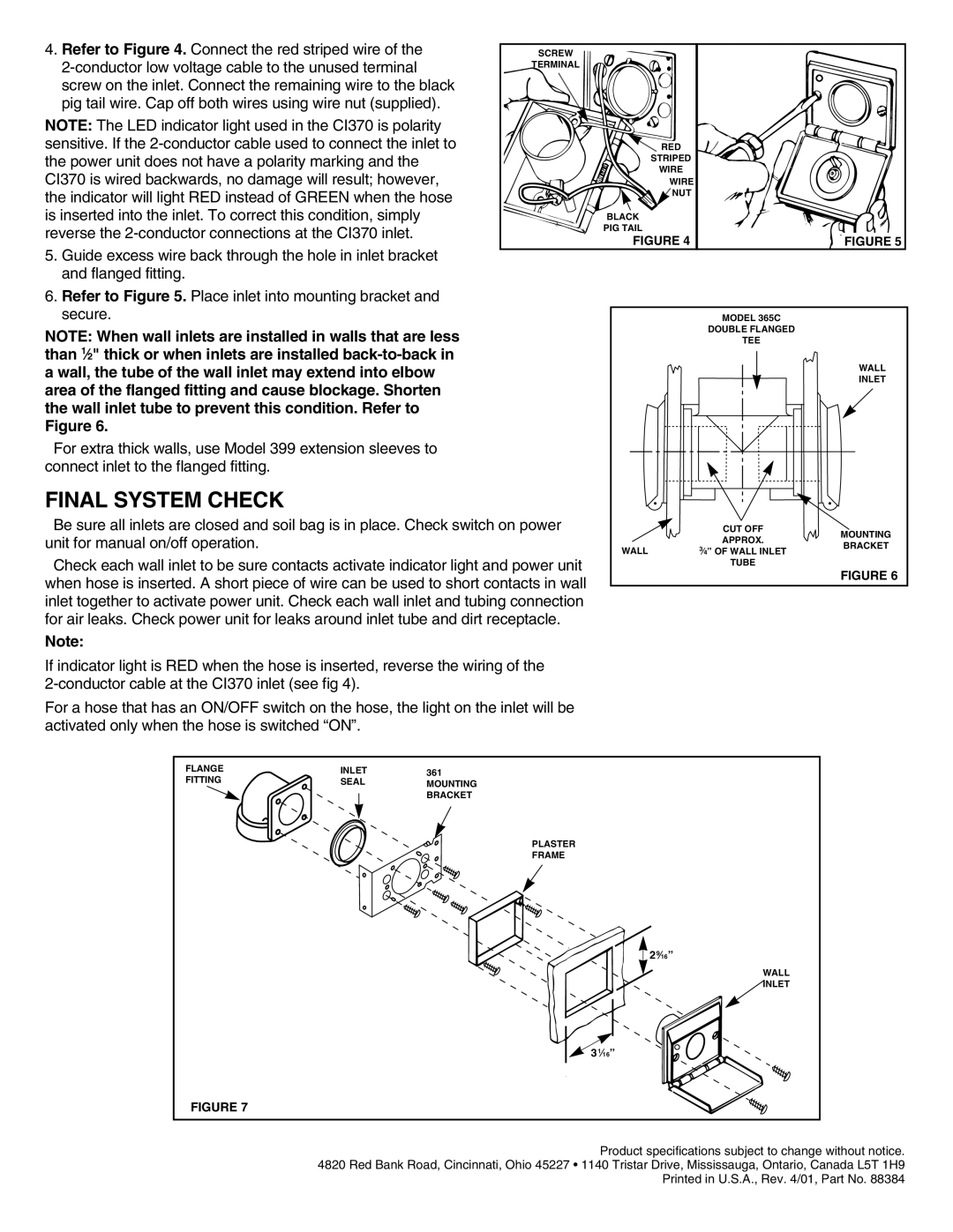
4. Refer to Figure 4. Connect the red striped wire of the | SCREW |
|
|
|
TERMINAL |
|
|
| |
|
|
|
| |
screw on the inlet. Connect the remaining wire to the black |
|
|
|
|
pig tail wire. Cap off both wires using wire nut (supplied). |
|
|
|
|
NOTE: The LED indicator light used in the CI370 is polarity |
|
|
|
|
sensitive. If the |
| RED |
|
|
the power unit does not have a polarity marking and the |
| STRIPED |
|
|
| WIRE |
|
| |
CI370 is wired backwards, no damage will result; however, |
|
|
| |
| WIRE |
|
| |
the indicator will light RED instead of GREEN when the hose |
| NUT |
|
|
|
|
|
| |
is inserted into the inlet. To correct this condition, simply |
| BLACK |
|
|
reverse the |
| PIG TAIL |
|
|
| FIGURE 4 |
| FIGURE 5 | |
5. Guide excess wire back through the hole in inlet bracket |
|
| ||
|
|
|
| |
and flanged fitting. |
|
|
|
|
6. Refer to Figure 5. Place inlet into mounting bracket and |
|
|
|
|
secure. |
|
| MODEL 365C |
|
NOTE: When wall inlets are installed in walls that are less |
|
| DOUBLE FLANGED |
|
|
| TEE |
| |
than 1⁄2" thick or when inlets are installed |
|
|
| WALL |
a wall, the tube of the wall inlet may extend into elbow |
|
|
| |
|
|
| INLET | |
area of the flanged fitting and cause blockage. Shorten |
|
|
| |
|
|
|
| |
the wall inlet tube to prevent this condition. Refer to |
|
|
|
|
Figure 6. |
|
|
|
|
For extra thick walls, use Model 399 extension sleeves to |
|
|
|
|
connect inlet to the flanged fitting. |
|
|
|
|
FINAL SYSTEM CHECK |
|
|
|
|
Be sure all inlets are closed and soil bag is in place. Check switch on power |
| CUT OFF | MOUNTING | |
unit for manual on/off operation. |
|
| APPROX. | |
|
| BRACKET | ||
| WALL | 3⁄4” OF WALL INLET | ||
Check each wall inlet to be sure contacts activate indicator light and power unit |
| TUBE |
| |
|
| FIGURE 6 | ||
when hose is inserted. A short piece of wire can be used to short contacts in wall |
|
| ||
|
|
| ||
inlet together to activate power unit. Check each wall inlet and tubing connection |
|
|
| |
for air leaks. Check power unit for leaks around inlet tube and dirt receptacle. |
|
|
| |
Note: |
|
|
|
|
If indicator light is RED when the hose is inserted, reverse the wiring of the
For a hose that has an ON/OFF switch on the hose, the light on the inlet will be activated only when the hose is switched “ON”.
FLANGE | INLET | 361 |
FITTING | SEAL | MOUNTING |
|
| BRACKET |
|
| PLASTER |
|
| FRAME |
|
| 29⁄16” |
|
| WALL |
|
| INLET |
|
| 31⁄16” |
FIGURE 7 |
|
|
Product specifications subject to change without notice. 4820 Red Bank Road, Cincinnati, Ohio 45227 • 1140 Tristar Drive, Mississauga, Ontario, Canada L5T 1H9 Printed in U.S.A., Rev. 4/01, Part No. 88384