INSTALLATION INSTRUCTIONS
READ & SAVE THESE INSTRUCTIONS!
QuieTTest® Combination Fan/Light
(with Night Light) MODEL: QT140L
SUITABLE FOR USE OVER TUB OR SHOWER ENCLOSURE WHEN INSTALLED IN A GFCI PROTECTED BRANCH CIRCUIT.
•Suitable for use with
•Not for use in kitchens.
•Uses standard 31⁄4" x 10" ducting.
•Designed for ceiling installation.
IMPORTANT SAFETY INSTRUCTIONS
WARNING: TO REDUCE THE RISK OF FIRE. ELECTRIC SHOCK, OR INJURY TO PERSONS, OBSERVE THE FOLLOWING:
A. Use this unit only in the manner intended by the manufacturer. If you have questions, contact the manufacturer.
B. Before servicing or cleaning unit, switch power off at service panel and lock service panel to prevent power from being switched on accidentally.
When the service disconnecting means cannot be locked, securely fasten a prominent warning device, such as a tag, to the service panel.
CAUTION:
For general ventilating use only. Do not use to exhaust hazardous or explosive materials and vapors.
INSTALLATION INSTRUCTIONS
WARNING: TO REDUCE THE RISK OF FIRE, ELECTRIC SHOCK, OR INJURY TO PERSONS, OBSERVE THE FOLLOWING:
A. Installation work and electrical wiring must be done by qualified person(s) in accordance with all applicable codes and standards, including
B. Sufficient air is needed for proper combustion and exhausting of gases through the flue (chimney) of fuel burning equipment to prevent back draft. Follow the heating equipment manufacturer’s guideline and safety standards such as those published by the National Fire Protection Association (NFPA), and the American Society for Heating, Refrigeration, and Air Conditioning Engineers (ASHRAE), and the local code authorities.
C. When cutting or drilling into wall or ceiling, do not damage electrical wiring and other hidden utilities.
D. Ducted fans must always be vented to the outdoors.
E. If this unit is to be installed over a tub or shower, it must be marked as appropriate for the application.
F. NEVER place a switch where it can be reached from a tub or shower.
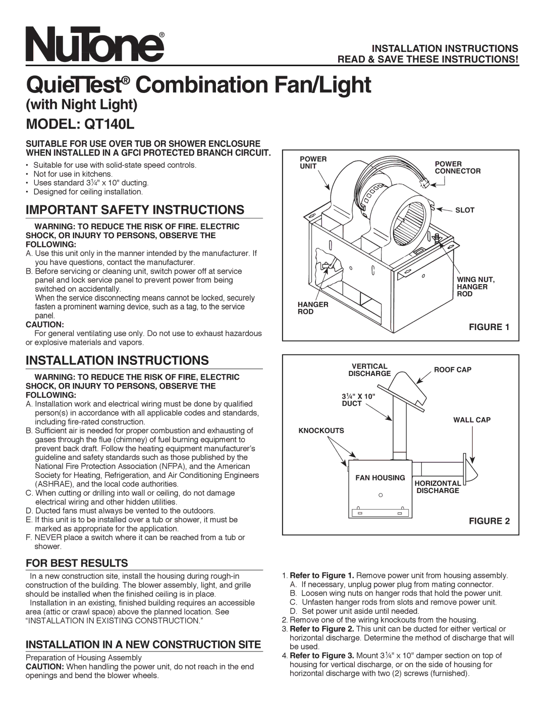
POWER | POWER | |
UNIT | ||
CONNECTOR | ||
| ||
| SLOT |
WING NUT,
HANGER
ROD
HANGER
ROD
FIGURE 1
VERTICAL | ROOF CAP | |
DISCHARGE | ||
|
31⁄4" X 10"
DUCT
WALL CAP
KNOCKOUTS
FAN HOUSING
HORIZONTAL
DISCHARGE
FIGURE 2
FOR BEST RESULTS
In a new construction site, install the housing during
Installation in an existing, finished building requires an accessible area (attic or crawl space) above the planned location. See
“INSTALLATION IN EXISTING CONSTRUCTION.”
INSTALLATION IN A NEW CONSTRUCTION SITE
Preparation of Housing Assembly
CAUTION: When handling the power unit, do not reach in the end openings and bend the blower wheels.
1.Refer to Figure 1. Remove power unit from housing assembly.
A.If necessary, unplug power plug from mating connector.
B.Loosen wing nuts on hanger rods that hold the power unit.
C.Unfasten hanger rods from slots and remove power unit.
D.Set power unit aside until needed.
2.Remove one of the wiring knockouts from the housing.
3.Refer to Figure 2. This unit can be ducted for either vertical or horizontal discharge. Determine the method of discharge that will be used.
4.Refer to Figure 3. Mount 31⁄4" x 10" damper section on top of housing for vertical discharge, or on the side of housing for horizontal discharge with two (2) screws (furnished).