DPG3000 Digital Pressure Gauge instructions
All units are factory calibrated prior to shipment.
1) ZERO TRIMMING:
Loosen the set screw retaining the front cover and rotate counter- clockwise to remove. You will now have access to the zero adjust potentiometer which is marked with a “Z”. An ideal zero is indicated by a reading of 000 with an intermittently flashing
A jeweler screwdriver or an eyeglass screwdriver is a suitable instrument. Be careful NOT to touch the “S” pot to the right, as changing this adjustment will invalidate the factory calibration.
2)BATTERY REPLACEMENT:
After removing the front cover as in 1), loosen the small set screw at the bottom of the Display Assembly and remove the Assembly from the Housing (be careful of the Sensor Leads). The batteries can now be pulled from the holders and replaced with P/N
3)RE-CALIBRATION
This procedure requires a known pressure source of at least
4)PROCEDURE:
A)With 0 psig applied (port vented) adjust zero as per instructions in #1.
B)Apply
C)
D)Repeat steps B) and C) until no further adjustment is required.
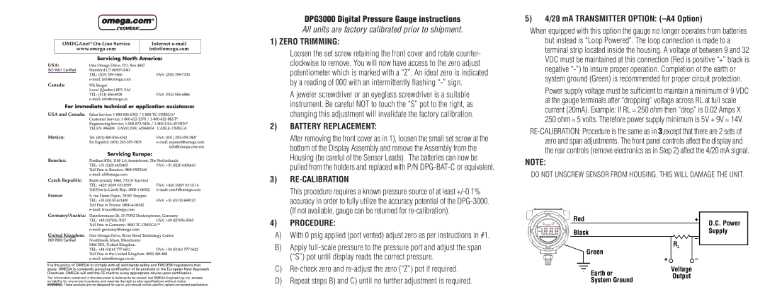
5)4/20 mA TRANSMITTER OPTION: (–A4 Option)
When equipped with this option the gauge no longer operates from batteries but instead is “Loop Powered”. The loop connection is made to a terminal strip located inside the housing. A voltage of between 9 and 32 VDC must be maintained at this connection (Red is positive “+” black is negative
Power supply voltage must be sufficient to maintain a minimum of 9 VDC at the gauge terminals after “dropping” voltage across RL at full scale current (20mA). Example: If RL = 250 ohm then “drop” is 0.02 Amps X 250 ohm = 5 volts. Therefore power supply minimum is 5V + 9V = 14V.
NOTE:
DO NOT UNSCREW SENSOR FROM HOUSING, THIS WILL DAMAGE THE UNIT.
ZS | Red | + | D.C. Power |
Kg/Cm2 |
|
| |
LOBAT | Black |
| Supply |
| – | ||
|
|
| |
| Green | RL |
|
| – |
| |
| + |
|
Earth or | Voltage | |
Output | ||
System Ground | ||
|