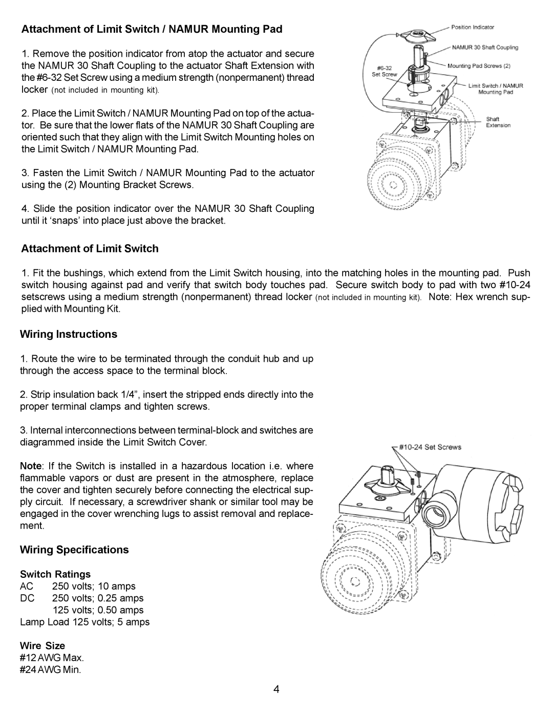
BVLS Series specifications
The Omega Engineering BVLS Series represents a significant advancement in the field of process instrumentation, designed to meet the demanding needs of modern industrial applications. Known for their precision and reliability, the BVLS Series level sensors are equipped with features that make them ideal for monitoring liquid levels in various environments.One of the main features of the BVLS Series is its robust construction, which is essential for ensuring long-lasting performance in harsh conditions. These sensors are made with durable materials that can withstand extreme temperatures and pressures, making them suitable for both indoor and outdoor use.
A notable aspect of the BVLS Series is its use of advanced non-contact level measurement technology. By utilizing ultrasonic or radar principles, the sensors can accurately measure the level of liquids without the need for direct contact. This characteristic helps to prevent contamination of the liquids being measured, making the BVLS Series an excellent choice for applications in the food and pharmaceutical industries where hygiene is paramount.
Another technological highlight of the BVLS Series is its digital output capability. The sensors feature a user-friendly interface, making them easy to program and configure. The digital output also allows for seamless integration with various control systems, enhancing their versatility. Users can choose from analog or digital communication methods, including 4-20 mA and Modbus protocols, depending on their specific requirements.
The BVLS Series is designed with user convenience in mind. Many units are equipped with visual indicators, such as LED displays, which provide real-time information about the level readings. This feature simplifies monitoring and reduces the need for additional external devices.
In terms of characteristics, the BVLS sensors boast high accuracy and resolution, ensuring that even small changes in liquid levels are detected reliably. They also have quick response times, which is critical in dynamic process environments. Furthermore, the adjustable range settings allow for customization to suit different applications and materials.
Overall, the Omega Engineering BVLS Series combines durability, precision, and ease of use, making it a preferred choice for industries that require reliable liquid level measurement. Its innovative technologies and robust features ensure that the BVLS Series can operate effectively in various challenging environments. Whether used in water treatment facilities, chemical processing, or oil and gas applications, these level sensors provide peace of mind through their dependable performance.

