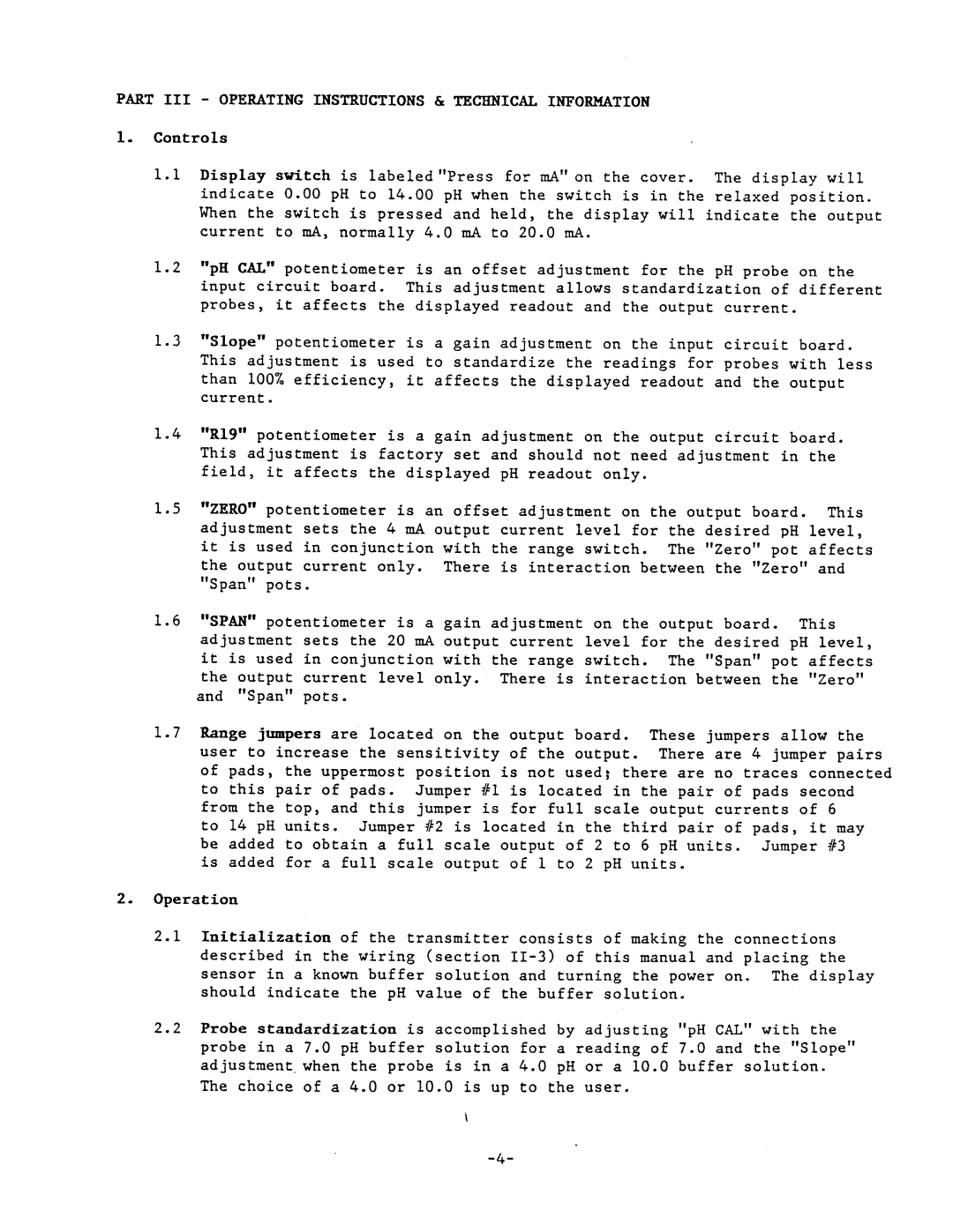
PHTX-11 specifications
Omega Engineering PHTX-11 is an advanced temperature and pressure transmitter known for its robust design and high performance in various industries. The PHTX-11 is specifically designed to measure temperature and pressure accurately, making it an ideal choice for applications in process control, HVAC systems, and various manufacturing processes.One of the main features of the PHTX-11 is its wide measurement range, capable of handling extreme temperatures and pressures. This versatility allows it to be used in a broad spectrum of applications, from food processing to chemical production. The device can function effectively in harsh environments, ensuring reliability and precision even under challenging conditions.
The PHTX-11 utilizes state-of-the-art sensing technologies to deliver high accuracy and fast response times. The temperature measurement is based on either thermocouple or RTD sensors, depending on the specific needs of the application. This flexibility allows users to choose the most suitable sensor for their requirements, enhancing the overall efficiency of the system.
Moreover, the pressure measurement in the PHTX-11 is achieved through high-quality piezo-resistive sensors, which provide superior performance and durability. These sensors are resistant to changes in temperature and can withstand overpressure conditions, ensuring long-term reliable service.
The PHTX-11 also features a user-friendly interface, making it easy to configure and calibrate. The digital display allows for real-time monitoring and provides valuable insights into system performance. Additionally, the transmitter supports various communication protocols, including analog outputs, which facilitate integration into existing control systems.
Another significant characteristic of the PHTX-11 is its compact and robust design. It is built in a rugged housing that meets high protection standards, such as NEMA and IP ratings, ensuring it can endure demanding industrial environments. This durability reduces downtime and maintenance costs, contributing to a more efficient operation.
In summary, Omega Engineering's PHTX-11 is a highly effective and versatile temperature and pressure transmitter. With its advanced sensing technologies, wide measurement range, user-friendly features, and rugged construction, it stands out as a top choice for industries that require dependable measurement solutions. Its capability to integrate seamlessly with various systems further enhances its appeal to engineers seeking reliable instrumentation in their processes.

