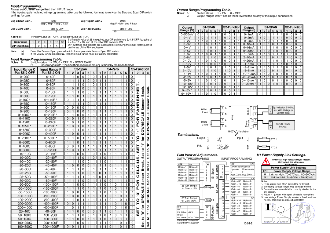
Input Programming.

Always set OUTPUT range first, then INPUT range.

If the Input range is not listed in the programming table, use the following formulae to work out the Zero and Span DIP switch settings for gain.

Deg C Span Gain =


1200


Deg F Spain Gain =


2400


deg C High - deg C Low


deg F High - deg F Low


Deg C Zero Gain =


deg C Low


Deg F Zero Gain =


deg F Low


5


10


If Zero is:

1/ Positive, put S5-1 OFF. 2/ Negative, put S5-1 ON.


So if a gain value of 28 is required, put DIP switch No's 3, 4, 5 OFF (ie, gains of

Gain Value

1

2


4

8

16

32


4 + 8 + 16 = 28) and all the other DIP switches ON.

DIP Switch No.

1

2


3

4

5

6


DIP switches and trimpots are accessed by removing the small rectangular lid


on the top of the PI-N enclosure


Note: (a) Enter the Zero or Span gain value into the appropriate Zero or Span DIP switch.

(b)If the ZERO GAIN exceeds 63, then the input range must be factory calibrated.

Input Range Programming Table.

Notes: 1/ Switch status 1 = ON, 0 = OFF, X = DON'T CARE.

2/ Input ranges with '*' beside them require more adjustment by the Span trimpot.

Output Range Programming Table.

Notes: 1/

Switch status 1 = ON 0 = OFF.

2/

Output ranges with '*' beside them reverse the polarity of the output connections.


Output


S1-SPAN


S2-Function

Output


S1-SPAN


S2-Function


Range (V)


1

2

3

4

5

6


1

2

3

4

Range (I)


1

2

3

4

5

6


1

2

3

4


0~500mV


0

1

1

1

1

1


0

0

1

1

0~1mA


0

1

1

1

1

1


0

0

0

0


0~1V


1

0

1

1

1

1


0

0

1

1

0~2mA


1

0

1

1

1

1


0

0

0

0


0~2V


1

1

0

1

1

1


0

0

1

1

0~5mA


0

1

0

1

1

1


0

0

0

0


0~3V


1

0

0

1

1

1


0

0

1

1

0~10mA


1

0

1

0

1

1


0

0

0

0


0~4V


1

1

1

0

1

1


0

0

1

1

0~16mA


1

1

1

1

0

1


0

0

0

0


0~5V


1

0

1

0

1

1


0

0

1

1

0~20mA


1

1

0

1

0

1


0

0

0

0


0~6V


1

1

0

0

1

1


0

0

1

1

1~5mA


1

1

0

1

1

1


1

0

0

0


0~8V


1

1

1

1

0

1


0

0

1

1

2~10mA


1

1

1

0

1

1


1

0

0

0


0~10V


1

1

0

1

0

1


0

0

1

1

4~20mA


1

1

1

1

0

1


1

0

0

0


0~12V


1

1

1

0

0

1


0

0

1

1

-1~1mA


1

0

1

1

1

1


0

1

0

0


Input Range C

Input Range F


Put S5-2 OFF

Put S5-2 ON


0~20C

0~40F


0~25C

0~50F


0~30C

0~60F


0~40C

0~80F


0~50C

0~100F


0~60C

0~120F


0~70C *

0~140F *


0~75C

0~150F

S3-Span

1

2

3

4

5

6

1

1

0

0

0

0

1

1

1

1

0

0

1

1

1

0

1

0

1

0

0

0

0

1

1

1

1

0

0

1

1

1

0

1

0

1

0

1

1

1

0

1

1

1

1

1

0

1

S4-Zero

1

2

3

4

5

6

1

1

1

1

1

1

1

1

1

1

1

1

1

1

1

1

1

1

1

1

1

1

1

1

1

1

1

1

1

1

1

1

1

1

1

1

1

1

1

1

1

1

1

1

1

1

1

1

S5-Function

1

2

3

4


X


X


FAHRENHEIT.

Sensor Break.

Sensor Break.


X


X


X


X


X


X


1~5V

1

1

1

0


1

1

1

0

1

1

-2~2mA

1

1

0

1

1

1

0

1

0

0


2~10V


1

1

1

1

0

1


1

0

1

1

-5~5mA


1

0

1

0

1

1


0

1

0

0


-1~1V


1

1

0

1

1

1


0

1

1

1

-10~10mA


1

1

0

1

0

1


0

1

0

0


-2~2V


1

1

1

0


1

1


0

1

1

1

-20~20mA


1

1

1

0

1

0


0

1

0

0


-5~5V


1

1

0

1

0

1


0

1

1

1

0~-10mA *


1

0

1

0

1

1


0

0

0

0


-10~10V


1

1

1

0


1

0


0

1

1

1

0~-20mA *


1

1

0

1

0

1


0

0

0

0


-12~12V


1

1

1

1

0

0


0

1

1

1


0~-5V *


1

0 1

0

1

1


0

0

1

1


0~-10V *


1

1

0

1

0

1


0

0

1

1


0~80C

0~160F


0~90C

0~180F


0~100C *

0~200F *


0~110C

0~220F


0~120C

0~240F


0~125C *

0~250F *


0~150C

0~300F


0

0

0

0

1

1

0

1

0

0

1

1

1

1

0

0

1

1

0

0

1

0

1

1

1

0

1

0

1

1

1

0

1

0

1

1

1

1

1

0

1

1


1

1

1

1

1

1

1

1

1

1

1

1

1

1

1

1

1

1

1

1

1

1

1

1

1

1

1

1

1

1

1

1

1

1

1

1

1

1

1

1

1

1


X

'1' FOR

DOWNSCALE

DOWNSCALE

X

X

X

X

X

X


for

for


RTD 1 2 wire

RTD 2 2 wire


3

A


Output


2


+


4

B


Input


1


5

A


Power Supply


8


7


6

B


+


1600V

Isolation


-

Eg. Indicator, 2100-M,

+

etc. With Voltage or

Current Input.


~

AC/DC Power

-

~Source.

+

0~200C

0~400F

0~250C *

0~500F *

0~300C

0~600F

0~400C

0~800F

0~600C

0~1200F

1

0

0

1

1

1

0

1

0

1

1

1


1

1

0

1

1

1

0

0

1

1

1

1

1

0

1

1

1

1

1

1

1

1

1

1

1

1

1

1

1

1


1

1

1

1

1

1

1

1

1

1

1

1

1

1

1

1

1

1

X

SETTO

to '1'


X

to '0'


X

X

X


Set

Set


Terminations.

Output

1

+Ve

Input 3

A

RTD 1


2

-Ve

4

B


P/S

7

~AC/+DC

5

A

RTD 2


8

~AC/-DC

6

B

-10~10C

-20~20F

-10~20C

-20~40F

-10~40C

-20~80F

-20~20C

-40~40F

-20~30C

-40~60F

-25~25C

-50~50F

-25~50C

-50~100F

-30~20C

-60~40F

-50~50C

-100~100F

-50~100C

-100~200F

-50~150C

-100~300F

-100~100C

-200~200F

-100~200C

-200~400F

-200~200C

-400~400F

-200~400C

-400~800F

20~40C

40~80F

50~100C

100~200F

50~150C

100~300F

100~200C

200~400F

100~500C

200~1000F

1

1

0

0

0

0

1

1

1

0

1

0

1

1

1

0

0

1

1

0

0

0

0

1

1

1

1

0

0

1

1

1

1

0

0

1

1

1

1

1

0

1

1

1

1

0

0

1

1

1

0

0

1

1

1

1

1

0

1

1

1

0

0

1

1

1

1

0

0

1

1

1

1

1

0

1

1

1

0

0

1

1

1

1

1

0

1

1

1

1

1

1

0

0

0

0

1

1

1

0

0

1

1

1

0

0

1

1

1

1

0

0

1

1

0

0

1

1

1

1

1

0

1

1

1

1

1

0

1

1

1

1

1

0

1

1

1

1

1

1

0

1

1

1

1

1

0

1

1

1

0

1

0

1

1

1

0

1

0

1

1

1

1

0

0

1

1

1

1

0

1

0

1

1

1

0

1

0

1

1

1

0

1

0

1

1

1

1

0

1

0

1

1

1

0

1

0

1

1

1

1

0

1

0

1

1

1

0

1

0

1

1

0

1

1

1

1

0

1

0

1

1

1

0

1

0

1

1

1

1

0

1

0

1

1

1

0

1

0

1

1

TO '0' FORCELCIUS.


1

for UPSCALE Sensor Break.

for UPSCALE Sensor Break.

1

1

1

1

1

1

1

1

1

1

1

1


1

SET

'0'

'1'

0

0


to

to

0


0


Set

Set

0


Plan View of Adjustments.

OUTPUTPROGRAMMING


OFF

ON


ON

Span-S1


Function-S5


Gain =16

Gain = 0


5


Gain = 1

Gain = 0


1


Gain = 2

Gain = 0


2


Gain = 4

Gain = 0


3


Gain = 8

Gain = 0


4


Gain =32

Gain = 0


6

S


Zero-S4


25 Turn Trimpot


for Span ±10%


Span


25 Turn Trimpot


Z


for Zero ±10%


Zero


Span-S3


Function-S2


OFF


ON


ON


1


0% Offset

+20%


2


Offset


3


0% Offset

-50% Offset


4


Current O/P Voltage O/P

Current O/P Voltage O/P

INPUT PROGRAMMING

4

OFF

ON

Downscale Upscale

3

Upscale

Downscale

2

C

F

1Poss Zero Neg Zero

ON

OFF

ON

6

Gain = 32

Gain = 0

5

Gain = 16

Gain = 0

4

Gain = 8

Gain = 0

3

Gain = 4

Gain = 0

2

Gain = 2

Gain = 0

1

Gain = 1

Gain = 0

ON

OFF

ON


6

Gain = 32

Gain = 0

5

Gain = 16

Gain = 0

4

Gain = 8

Gain = 0

3

Gain = 4

Gain = 0

2

Gain = 2

Gain = 0

1

Gain = 1

Gain = 0

ON


10.04-2


H1 Power Supply Link Settings.


WARNING: High Voltages Maybe Present.


Only adjust link with power


disconnected.


Power Supply Link Settings


H1

Power Supply Voltage Range


HLink for High: 70~270Vac / 80~380Vdc

M Link for Mid: 24~80Vac / 20~90Vdc

Notes:

1/ H1 is approx 4cm (1½") behind the 'S' trimpot. 2/ Exceeding voltage ranges may damage the unit.

3/ Ensure the enclosure label is correctly labelled for the link position.

4/ Adjust H1 jumper with a pair of needle nose pliers. 5/ Low Voltage Power Supply version is fixed, and has

no link. This must be ordered separately.

H 1

M I D

H I G H

M

H


M


S 1 - SP A N S Z S 2 - F U N C T


H

Page 4
Image 4
Omega Engineering TX801D RTD manual Input Programming, Input Range Programming Table, Output Range Programming Table

TX801D RTD specifications

The Omega Engineering TX801D RTD is a remarkable temperature sensing device widely recognized for its accuracy, durability, and advanced features. As part of Omega's extensive line of temperature measurement solutions, the TX801D is specifically designed to provide reliable temperature readings in industrial and scientific applications.

One of the main features of the TX801D RTD is its high precision measurement capability. With a nominal resistance of 100 ohms at 0°C, it delivers outstanding accuracy in temperature measurements. The device typically conforms to the Class A tolerance as per IEC 60751 standards, ensuring a precision of ±0.15°C over the standard temperature range. This precision makes it ideal for processes requiring stringent temperature control.

The TX801D utilizes a thin-film technology for its sensing element, which contributes to its quick response time and exceptional stability. Thin-film RTDs are known for their robustness and reliability, delivering consistent performance even in harsh environments. Furthermore, the device exhibits excellent linearity, enhancing its capability to be used in various applications without the need for extensive calibration.

Temperature range is a crucial characteristic of any RTD sensor. The TX801D can measure temperatures ranging from -200°C to 650°C, making it suitable for a wide array of applications in industries such as HVAC, food processing, and chemical manufacturing. This versatility enables users to implement the TX801D in diverse setups, from cryogenic temperatures to high-heat environments.

In terms of construction, the TX801D RTD is available in a variety of configurations, including different probe lengths, diameters, and materials such as stainless steel. This customization allows for optimal installation in various environments, whether it be in liquid, gas, or solid mediums. The sensor head can also be fitted with various connectors to ensure compatibility with existing measurement systems.

Another significant feature of the TX801D RTD is its robust protection against environmental factors. Depending on the selected housing and materials, the RTD can withstand humidity, pressure, and even corrosive substances, attributing to its lasting performance and decreasing maintenance needs.

In conclusion, the Omega Engineering TX801D RTD combines precision, durability, and versatility, making it an excellent choice for a wide range of temperature measuring applications. Its advanced thin-film technology, wide temperature range, and robust construction characteristics position it as a reliable sensor in both industrial and scientific fields. With the TX801D, users can be confident in their temperature measurements, promoting efficiency and safety in their operations.