SAFETY PRECAUTIONS
Step Two
 About this Manual:
PLEASE READ THE ENTIRE MANUAL PRIOR TO INSTALLING OR USING THIS PRODUCT. This manual includes information on all models of horizontal mini-float level switches from OMEGA ENGINEERING, LVH-200 series. Please refer to the part number located on the switch label to verify the exact model which you have purchased.
 User’s Responsibility for Safety:
INSTALLATION
Step Three
Through Wall Installation:
OMEGA ENGINEERING’s LVH-200 series sensors may be installed through the side wall of a tank. The LVH-200 series has dual male 1/2" NPT threads for installation from the outside of the tank in or the inside of the tank out. If the LVH-200 series is installed in the Outside-In method, then the outer threads may be used for connection
ELECTRICAL
Step Four
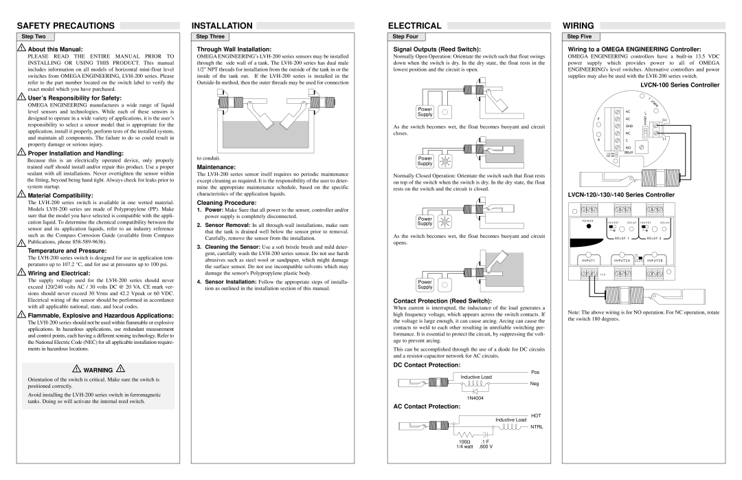
Signal Outputs (Reed Switch):
Normally Open Operation: Orientate the switch such that float swings down when the switch is dry. In the dry state, the float rests in the lowest position and the circuit is open.
WIRING
Step Five
Wiring to a OMEGA ENGINEERING Controller:
OMEGA ENGINEERING controllers have a built-in 13.5 VDC power supply which provides power to all of OMEGA ENGINEERING's level switches. Alternative controllers and power supplies may also be used with the LVH-200 series switch.
LVCN-100 Series Controller
OMEGA ENGINEERING manufactures a wide range of liquid level sensors and technologies. While each of these sensors is designed to operate in a wide variety of applications, it is the user’s responsibility to select a sensor model that is appropriate for the application, install it properly, perform tests of the installed system, and maintain all components. The failure to do so could result in property damage or serious injury.
 Proper Installation and Handling:
Because this is an electrically operated device, only properly trained staff should install and/or repair this product. Use a proper sealant with all installations. Never overtighten the sensor within the fitting, beyond being hand tight. Always check for leaks prior to system startup.
to conduit.
Maintenance:
The LVH-200 series sensor itself requires no periodic maintenance except cleaning as required. It is the responsibility of the user to deter- mine the appropriate maintenance schedule, based on the specific
Power
Supply
As the switch becomes wet, the float becomes buoyant and circuit closes.
Power
Supply
Normally Closed Operation: Orientate the switch such that float rests on top of the switch when the switch is dry. In the dry state, the float rests on the switch and the circuit is closed.
 Material Compatibility:
The LVH-200 series switch is available in one wetted material. Models LVH-200 series are made of Polypropylene (PP). Make sure that the model you have selected is compatible with the appli- cation liquid. To determine the chemical compatibility between the sensor and its application liquids, refer to an industry reference such as the Compass Corrosion Guide (available from Compass  Publications, phone 858-589-9636).
Temperature and Pressure:
The LVH-200 series switch is designed for use in application tem- peratures up to 107.2 °C, and for use at pressures up to 100 psi.
 Wiring and Electrical:
The supply voltage used for the LVH-200 series should never exceed 120/240 volts AC / 30 volts DC @ 20 VA. CE mark ver- sions should never exceed 30 Vrms and 42.2 Vpeak or 60 VDC. Electrical wiring of the sensor should be performed in accordance with all applicable national, state, and local codes.
 Flammable, Explosive and Hazardous Applications:
The LVH-200 series should not be used within flammable or explosive applications. In hazardous applications, use redundant measurement and control points, each having a different sensing technology. Refer to the National Electric Code (NEC) for all applicable installation require- ments in hazardous locations.
 WARNING
Orientation of the switch is critical. Make sure the switch is positioned correctly.
Avoid installing the LVH-200 series switch in ferromagnetic tanks. Doing so will activate the internal reed switch.
characteristics of the application liquids.
Cleaning Procedure:
1.Power: Make Sure that all power to the sensor, controller and/or power supply is completely disconnected.
2.Sensor Removal: In all through-wall installations, make sure that the tank is drained well below the sensor prior to removal. Carefully, remove the sensor from the installation.
3.Cleaning the Sensor: Use a soft bristle brush and mild deter- gent, carefully wash the LVH-200 series sensor. Do not use harsh abrasives such as steel wool or sandpaper, which might damage the surface sensor. Do not use incompatible solvents which may damage the sensor's Polypropylene plastic body.
4.Sensor Installation: Follow the appropriate steps of installa- tion as outlined in the installation section of this manual.
Power
Supply
As the switch becomes wet, the float becomes buoyant and circuit opens.
Power
Supply
Contact Protection (Reed Switch):
When current is interrupted, the inductance of the load generates a high frequency voltage, which appears across the switch contacts. If the voltage is large enough, it can cause arcing. Arcing can cause the contacts to weld to each other resulting in unreliable switching per- formance. It is essential to protect the circuit, by suppressing the volt- age to prevent arcing.
This can be accomplished through the use of a diode for DC circuits and a resistor-capacitor network for AC circuits.
DC Contact Protection:
Pos
Inductive Load
Neg
1N4004
AC Contact Protection:
HOT
Inductive Load
NTRL
LVCN-120/-130/-140 Series Controller
P O W E R | I N V E R T | D E L AY | I N V E R T | D E L AY |
|
| | | | | | | | | | | | | | |
| | | | | | | | | | | | | | |
| --+ | | | | | --+ | | | |
| | | | | | | | | |
| | | | R E L AY 1 | | | | | R E L AY 2 | |
| | | | | | | L A | | | | | | |
I N P U T 1 | | | | | | | | | | | | | | |
| | | I N P U T 2 A O N O F F I N P U T 2 B |
T C H
Note: The above wiring is for NO operation. For NC operation, rotate the switch 180 degrees.