Omega Vehicle Security DP25-TH quick start manual Using This Quick Start Manual, Before You Begin

Models: DP25-TH

1 2
Download 2 pages 39.36 Kb
Page 1
Image 1
START HERE
92,00 + 0,81/Ð0,00
(3.622 + .032/Ð.000)
NOTE: Dimensions in Millimeters (Inches)

START HERE

Using This Quick Start Manual

Use this Quick Start Manual to set up your controller and begin operation. Information is provided on how to:

¥Connect ac power

¥Connect sensor input

¥Set basic options for operation

For complete information on all setup options, see the OperatorÕs Manual.

Before You Begin

In addition to the controller and the related parts, you will need the following items to set up your unit:

¥ac power

¥Sensor

2

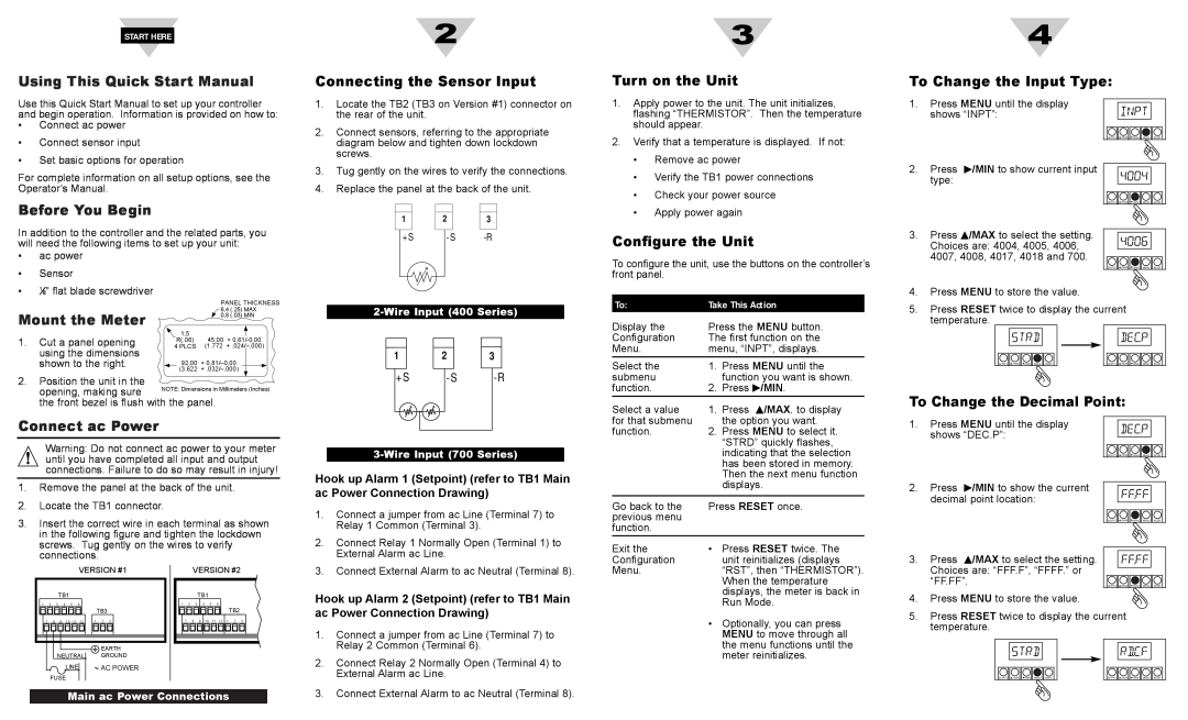
Connecting the Sensor Input

1.Locate the TB2 (TB3 on Version #1) connector on the rear of the unit.

2.Connect sensors, referring to the appropriate diagram below and tighten down lockdown screws.

3.Tug gently on the wires to verify the connections.

4.Replace the panel at the back of the unit.


1


2


3


+ S


- S

-R


3

Turn on the Unit

1.Apply power to the unit. The unit initializes, flashing ÒTHERMISTORÓ. Then the temperature should appear.

2.Verify that a temperature is displayed. If not:

¥Remove ac power

¥Verify the TB1 power connections

¥Check your power source

¥Apply power again

Configure the Unit

To configure the unit, use the buttons on the controllerÕs front panel.

4

To Change the Input Type:

1. Press MENU until the display


shows ÒINPTÓ:


SETPTS

/MAX

/MIN MENU RESET

2.Press /MIN to show current input type:

SETPTS /MAX /MIN MENU RESET

3.Press /MAX to select the setting. Choices are: 4004, 4005, 4006, 4007, 4008, 4017, 4018 and 700.

SETPTS /MAX /MIN MENU RESET

¥1Ú8Ó flat blade screwdriver

Mount the Meter

1.Cut a panel opening using the dimensions shown to the right.

PANEL THICKNESS


6,4

(.25)

MAX


0,8

(.03)

MIN

1,5


R(.06)

45,00 + 0,61/-0,00

4 PLCS

(1.772 + .024/Ð.000)

2-Wire Input (400 Series)


1


2


3


To:

Take This Action

Display the

Press the MENU button.

Configuration

The first function on the

Menu.

menu, ÒINPTÓ, displays.

Select the

1. Press MENU until the

4.Press MENU to store the value.

5.Press RESET twice to display the current temperature.

SETPTS

/MAX

/MIN

MENU

RESET

SETPTS

/MAX

/MIN

MENU

RESET

2.Position the unit in the

opening, making sure

the front bezel is flush with the panel.

+ S - S -R

submenu


function you want is shown.

function.

2.

Press

/MIN.

Select a value

1.

Press

/MAX. to display

To Change the Decimal Point:

Connect ac Power

Warning: Do not connect ac power to your meter until you have completed all input and output connections. Failure to do so may result in injury!

1.Remove the panel at the back of the unit.

2.Locate the TB1 connector.

3.Insert the correct wire in each terminal as shown in the following figure and tighten the lockdown screws. Tug gently on the wires to verify connections.

3-Wire Input (700 Series)

Hook up Alarm 1 (Setpoint) (refer to TB1 Main ac Power Connection Drawing)

1.

Connect a jumper from ac Line (Terminal 7) to


Relay 1 Common (Terminal 3).

2.

Connect Relay 1 Normally Open (Terminal 1) to


External Alarm ac Line.

for that submenu


the option you want.

function.

2.

Press MENU to select it.


ÒSTRDÓ quickly flashes,


indicating that the selection


has been stored in memory.


Then the next menu function


displays.


Go back to the

Press RESET once.

previous menu


function.


Exit the

¥

Press RESET twice. The

Configuration


unit reinitializes (displays

1.

Press MENU until the display


shows ÒDEC.PÓ:

2.

Press

/MIN to show the current


decimal point location:

3.

Press

/MAX to select the setting.

SETPTS /MAX /MIN MENU RESET

SETPTS /MAX /MIN MENU RESET

VERSION #1

1 2 3 4 5 6

VERSION #2


TB1


1

2

3

4

5

6


TB2

3. Connect External Alarm to ac Neutral (Terminal 8).

Hook up Alarm 2 (Setpoint) (refer to TB1 Main

Menu.

ÒRSTÓ, then ÒTHERMISTORÓ).


When the temperature


displays, the meter is back in


Run Mode.

Choices are: ÒFFF.FÓ, ÒFFFF.Ó or

ÒFF.FFÓ.

4. Press MENU to store the value.

SETPTS /MAX /MIN MENU RESET

7

8

9

1

2

3

EARTH

NEUTRAL GROUND

Using This Quick Start ManualLINEBefore You Begin AC POWER

FUSE

7

8

9

10

11

12

1

2

3


ac Power Connection Drawing)

1.

Connect a jumper from ac Line (Terminal 7) to


Relay 2 Common (Terminal 6).

2.

Connect Relay 2 Normally Open (Terminal 4) to


External Alarm ac Line.

¥ Optionally, you can press

MENU to move through all

the menu functions until the meter reinitializes.

5.Press RESET twice to display the current temperature.

SETPTS

/MAX

/MIN

MENU

RESET

SETPTS

/MAX

/MIN

MENU

RESET

Main ac Power Connections

3. Connect External Alarm to ac Neutral (Terminal 8).

Page 1
Image 1
Omega Vehicle Security DP25-TH quick start manual Using This Quick Start Manual, Before You Begin, Turn on the Unit