User’s Manual DRF Series
SIGNAL ADJUSTMENT
To proceed to adjust a range of input and output signals, first select with the appropriate jumpers, the signal ranges
which include your desired adjustment. Then proceed to the adjustment.
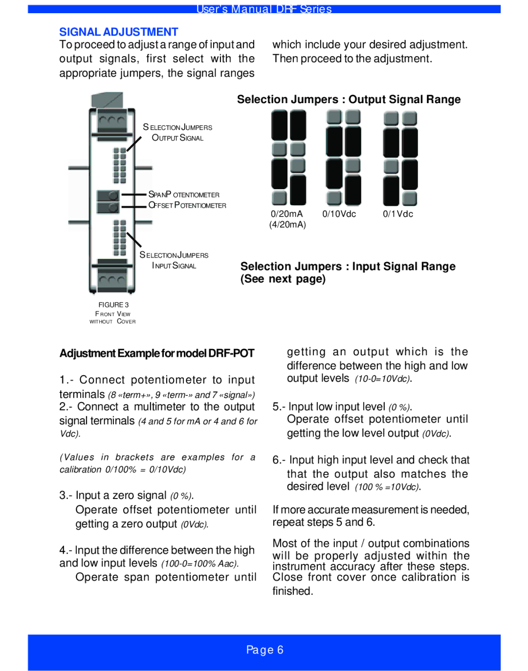
Selection Jumpers : Output Signal Range
SELECTIONJUMPERS OUTPUT SIGNAL
SPANP OTENTIOMETER
OFFSET POTENTIOMETER
0/20mA 0/10Vdc 0/1Vdc (4/20mA)
SELECTIONJUMPERS
I NPUT SIGNAL | Selection Jumpers : Input Signal Range |
| (See next page) |
FIGURE 3
F RONT VIEW
WITHOUT COVER
AdjustmentExampleformodelDRF-POT
1.- Connect potentiometer to input
terminals (8 «term+», 9
2.- Connect a multimeter to the output signal terminals (4 and 5 for mA or 4 and 6 for
Vdc).
(Values in brackets are examples for a calibration 0/100% = 0/10Vdc)
3.- Input a zero signal (0 %).
Operate offset potentiometer until getting a zero output (0Vdc).
4.- Input the difference between the high and low input levels
Operate span potentiometer until
getting an output which is the
difference between the high and low output levels
5.- Input low input level (0 %).
Operate offset potentiometer until getting the low level output (0Vdc).
6.- Input high input level and check that
that the output also matches the desired level (100 % =10Vdc).
If more accurate measurement is needed, repeat steps 5 and 6.
Most of the input / output combinations will be properly adjusted within the instrument accuracy after these steps. Close front cover once calibration is
finished.
Page 6