INSTALLATION OF PSW-141 PRESSURE

SWITCH

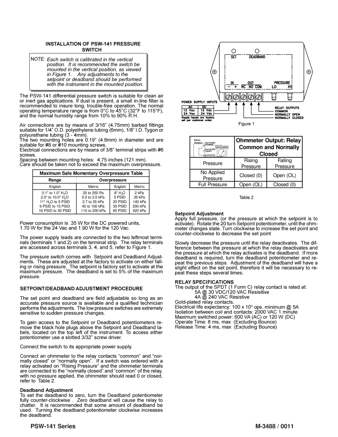
NOTE: Each switch is calibrated in the vertical position. It is recommended the switch be mounted in the vertical position, as viewed in Figure 1. Any adjustments to the setpoint or deadband should be performed with the instrument in the mounted position.

The PSW-141 differential pressure switch is suitable for clean air or inert gas applications. If dust is present, a small in-line filter is recommended to insure long, trouble-free operation. The normal operating temperature range is from 0°C to 45°C (32°F to 115°F), and the normal humidity range from 10% to 90% R.H.

Air connections are by means of 3/16” (4.75mm) barbed fittings suitable for 1/4” O.D. polyethylene tubing (6mm), 1/8” I.D. Tygon or polyurethane tubing (3 - 4mm).

The two mounting holes are 0.19” (4.8mm) in diameter and are suitable for #8 or #10 mounting screws.

Electrical connections are by means of 3/8” terminal strips with #6 screws.

Spacing between mounting holes: 4.75 inches (121 mm).

Care should be taken not to exceed the maximum overpressure.

Maximum Safe Momentary Overpressure Table

Range


Overpressure


English


Metric

English

Metric


0.1" to 1.0" H2O

25 to 250 Pa

8" H2O

2 kPa

2.0" to 10.0" H2O

0.5 to 2.5 kPa

5 PSID

35 kPa

11" H2O to 5

PSID

2.7 to 35 kPa

20 PSID

140 kPa

6 PSID to 15

PSID

40 to 100 kPa

30 PSID

200 kPa

16 PSID to 30 PSID

110 to 200 kPa

60 PSID

420 kPa


Power consumption is .35 W for the DC powered units, 1.70 W for the 24 Vac and 1.90 W for the 120 Vac.

The power supply leads are connected to the two leftmost termi- nals (terminals 1 and 2) on the terminal strip. The relay terminals are accessed across terminals 3, 4, and 5, refer to Figure 1.

The pressure switch comes with Setpoint and Deadband Adjust- ments. These are adjusted at the factory to activate on either fall- ing or rising pressure. The setpoint is factory set to activate at the maximum pressure. The deadband is set to 5% of the maximum pressure.

SETPOINT/DEADBAND ADJUSTMENT PROCEDURE

The set point and deadband are field adjustable so long as an accurate pressure source is available and a qualified technician performs the adjustments. The low pressure switches are extremely sensitive to sudden pressure changes.

To gain access to the Setpoint or Deadband potentiometers re- move the black hole plugs above the Setpoint and Deadband la- bels, located on the top left of the instrument. To access either potentiometer use a slotted 3/32” screw driver.

Connect the switch to its appropriate power supply.

Connect an ohmmeter to the relay contacts “common” and “nor- mally closed” or “normally open”. If a switch was ordered with a relay activated on “Rising Pressure” and the ohmmeter terminals are connected to the “normally closed” and “common” of the relay, with no pressure applied, the ohmmeter should read 0 or closed, refer to Table 2.

Deadband Adjustment

To set the deadband to zero, turn the Deadband potentiometer fully counter-clockwise . Zero deadband will cause the relay to chatter. It is recommended that some amount of deadband be used. Turning the deadband potentiometer clockwise increases the deadband.

Figure 1


Ohmmeter Output: Relay


Common and Normally


Closed

Pressure

Rising

Falling

Pressure

Pressure


No Applied

Closed (0)

Open (OL)

Pressure


Full Pressure

Open (OL)

Closed (0)

Table 2

Setpoint Adjustment

Apply full pressure, (or the pressure at which the setpoint is to activate). Rotate the 20 turn Setpoint potentiometer, until the ohm- meter changes state. Turn clockwise to increase the set point and counter-clockwise to decrease the set point

Slowly decrease the pressure until the relay deactivates. The dif- ference between the pressure at which the relay deactivates and the pressure at which the relay activates is the deadband. If more deadband is required, turn the deadband potentiometer and re- peat the previous steps. Adjustment of the deadband will have a slight effect on the set point, therefore it will be necessary to re- peat these steps several times.

RELAY SPECIFICATIONS

The output of the SPDT (1 Form C) relay contact is rated at: 5A @ 30 VDC/120 VAC Resisitive

4A @ 240 VAC Resistive Gold-plated relay contacts.

Electrical life expectancy: 100 x 103 ops. minimum @ 5A

Isolation between coil and contacts: 2000 VAC 1 minute

Maximum switched power: 600 VA (AC) or 120 W (DC)

Operate Time: 8 ms, max (Excluding Bounce)

Release Time: 4 ms, max (Excluding Bounce)

PSW-141 Series

M-3488 / 0011

Page 3
Image 3
Omega Vehicle Security PSW141 series manual PSW-141 Series

PSW141 series specifications

The Omega Vehicle Security PSW141 series is a cutting-edge vehicle security system designed to provide maximum protection against theft and unauthorized access. This state-of-the-art system incorporates advanced technology and features that ensure the safety and security of your vehicle and its contents.

One of the standout features of the PSW141 series is its robust immobilizer technology. The immobilizer works by preventing the engine from starting without the proper key or access code, rendering the vehicle inoperable to potential thieves. This feature is crucial in deterring vehicle theft and is a staple in modern security systems.

In addition to the immobilizer, the PSW141 series boasts a sophisticated alarm system that includes multiple sensors to detect any unauthorized entry or movement. The system can be equipped with shock sensors, door sensors, and even proximity sensors, all of which work together to provide comprehensive coverage. When an intrusion is detected, the alarm produces a loud siren, alerting the owner and deterring potential intruders.

Remote control functionality is another key characteristic of the PSW141 series. Vehicle owners can lock and unlock their vehicle remotely, as well as activate or deactivate the alarm system from a distance. The convenience of remote access enhances the user experience and allows for quick response in case of an attempted breach.

The PSW141 series also features vehicle tracking capabilities. In the unfortunate event that a vehicle is stolen, the tracking technology allows owners to locate their vehicle in real time. This feature significantly increases the chances of recovering a stolen vehicle and adds an extra layer of security for vehicle owners.

Installation of the Omega Vehicle Security PSW141 series can be performed by certified technicians, ensuring that the system is set up correctly and functions optimally. The system is compatible with a wide range of vehicles, making it a versatile choice for many users.

Overall, the Omega Vehicle Security PSW141 series combines advanced technology, user-friendly features, and robust security measures to protect vehicles against theft and unauthorized access. With its comprehensive approach to vehicle security, the PSW141 series stands out as a reliable choice for those looking to safeguard their vehicles effectively. Investing in the PSW141 series is an investment in peace of mind, knowing that your vehicle is well protected.