H Y D R A U L I C , P I S T O N - S T Y L E P R E S S U R E S W I T C H
SWITCH SELECTION AND MOUNTING INSTRUCTIONS
•Select a switch such that the desired switching point falls roughly in the middle of the adjustment range.
•Do not exceed switch electrical ratings. Use an appropriately sized relay when switching larger electrical loads.
•For liquid media with pressure spikes and/or pulsating pressures, install a pressure snubber.
•For outdoor applications, sufficient protection must be provided.
Adjustment Of Switching Points
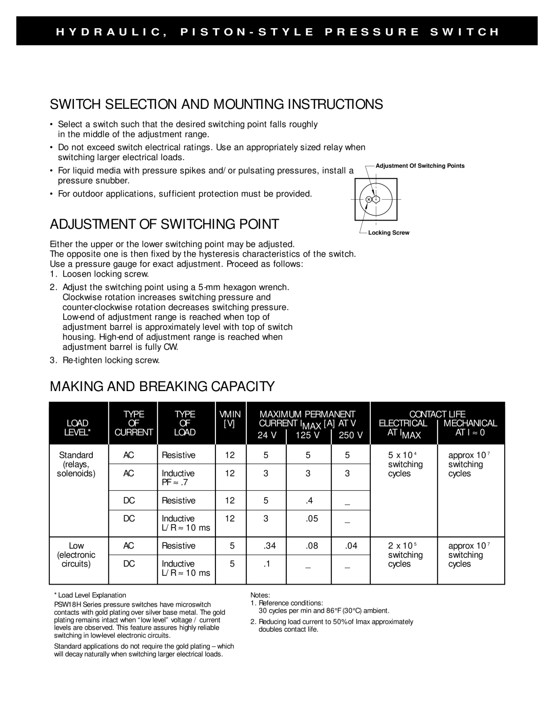
ADJUSTMENT OF SWITCHING POINT
Locking Screw
Either the upper or the lower switching point may be adjusted.
The opposite one is then fixed by the hysteresis characteristics of the switch.
Use a pressure gauge for exact adjustment. Proceed as follows:
1.Loosen locking screw.
2.Adjust the switching point using a
3.
MAKING AND BREAKING CAPACITY
|
|
|
|
|
|
|
|
|
|
|
|
| TYPE | TYPE | VMIN | MAXIMUM PERMANENT | CONTACT LIFE | ||||||
LOAD | OF | OF | [V] | CURRENT IMAX [A] AT V | ELECTRICAL |
| MECHANICAL | ||||
| |||||||||||
LEVEL* | CURRENT | LOAD |
| 24 V |
| 125 V |
| 250 V | AT IMAX |
| AT I ≈ 0 |
|
| ||||||||||
|
|
| |||||||||
Standard | AC | Resistive | 12 | 5 |
| 5 |
| 5 | 5 x 10⁴ |
| approx 107 |
(relays, |
|
|
|
|
|
|
|
| switching |
| switching |
|
|
|
|
|
|
|
|
| |||
solenoids) | AC | Inductive | 12 | 3 |
| 3 |
| 3 | cycles |
| cycles |
|
| PF ≈ .7 |
|
|
|
|
|
|
|
|
|
|
|
|
|
|
|
|
|
|
|
|
|
| DC | Resistive | 12 | 5 |
| .4 |
| _ |
|
|
|
|
|
|
|
|
|
|
|
|
|
|
|
| DC | Inductive | 12 | 3 |
| .05 |
| _ |
|
|
|
|
| L/R ≈ 10 ms |
|
|
|
|
|
|
|
|
|
|
|
|
|
|
|
|
|
|
|
|
|
Low | AC | Resistive | 5 | .34 |
| .08 |
| .04 | 2 x 10⁵ |
| approx 107 |
(electronic |
|
|
|
|
|
|
|
| switching |
| switching |
|
|
|
|
|
|
|
|
| |||
circuits) | DC | Inductive | 5 | .1 |
| _ |
| _ | cycles |
| cycles |
|
| L/R ≈ 10 ms |
|
|
|
|
|
|
|
|
|
|
|
|
|
|
|
|
|
|
|
|
|
*Load Level Explanation
PSW18H Series pressure switches have microswitch contacts with gold plating over silver base metal. The gold plating remains intact when “low level” voltage / current levels are observed. This feature assures highly reliable switching in
Standard applications do not require the gold plating – which will decay naturally when switching larger electrical loads.
Notes:
1.Reference conditions:
30 cycles per min and 86°F (30°C) ambient.
2.Reducing load current to 50% of Imax approximately doubles contact life.