Manuals
/
Omega Vehicle Security
/
Computer Equipment
/
Switch
Omega Vehicle Security
USB-4761
manual
1 I/O Connector Pin Assignment
Models:
USB-4761
1
28
39
39
Download
39 pages
13.85 Kb
25
26
27
28
29
30
31
32
Specs
Install
Signal Connections
Warranty
Configuring the Device
3.2 I/O Connectors
Setting Up the Device
Device Testing
Features
Page 28
Image 28
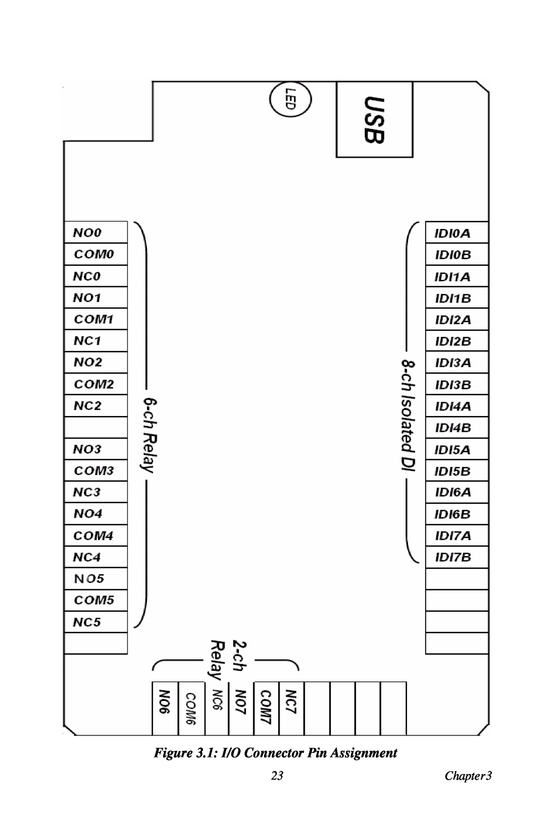
Figure 3.1: I/O Connector Pin Assignment
23
Chapter3
Page 27
Page 29
Page 28
Image 28
Page 27
Page 29
Contents
User’s Guide
USB-4761
8 Channel Relay/Isolated DI USB Data Acquisition Module
Shop online at
OMEGAnet Online Service omega.com
Internet e-mail info@omega.com
Servicing North America
For immediate technical or application assistance
8-channel Relay / Isolated DI USB Data Acquisition Module
User Manual
USB-4761
Signal Connections
Chapter
Contents
Installation
Appendix
A Specifications
B Function Block
Introduction
Features Applications Installation Guide Software Overview
1.1 Features
You can install up to sixteen USB-4761’s to a
The power output of an USB port is 500 mA
external power supply to support more than one
1.1.3 Reset Protection for Industrial Applications
1.1.1 Robust Protection
1.1.2 Wide Input Range
1.1.4 Plug & Play Function
1.3 Installation Guide
1.2 Applications
Figure 1.1 Installation Flow Chart
1.4.1 Programming Choices for DA&C Module
1.4 Software Overview
1.4.2 Device Drivers
1.5 Device Driver Programming
1.5.1 Programming Tools
Start/Programs/Omega USB-4700 Series/Device Driver’s Manual
C/Program Files/Omega/USB-4700/Examples
1.5.3 Troubleshooting Device Drivers Error
1.5.2 Programming with Device Drivers Function Library
Unpacking Driver Installation Hardware Installation
Installation
Device Setup & Configuration Device Testing Hardware Uninstallation
2.1 Unpacking
Chapter 2 Installation
After taking out the module, you should first
2.2 Driver Installation
If the auto-play function is not enabled on your
command to execute Setup.exe on the companion
computer, use Windows Explorer or Windows Run
2.3 Hardware Installation
Make sure you have installed the software driver
before you install the module please refer to
Section 2.2 Driver Installation
If your module is properly installed, you should
installed. In this case, remove the mod- ule from
the driver installation process again
Figure 2.2 Device Name on the Device Manager
2.4 Device Setup & Configuration
2.4.1 Setting Up the Device
2.4.2 Configuring the Device
Figure 2.4 Device Manager Dialog Box
can’t find it in Device Manager, please close the
Device Manager and restart it
2.5 Device Testing
Figure 2.5 The Device Setting Dialog Box
Please refer to the software manual
download utility guidance and further information
2.5.2 Testing Digital Output Function
2.5.1 Testing Digital Input Function
Figure 2.6 Digital Input Tab in Device Test Dialog
2.6 Hardware Uninstallation
Figure 2.7 Digital Output Tab in Device Test Dialog
Figure 2.9 Stop a Hardware device dialog box
Figure 2.8 Unplug or Eject Hardware Dialog
Step3 Select “USB4711 Device” and press “Stop” Button
some unexpected system errors or damages may hap
Please make sure that you have closed the application
programs before unplugging the USB device, otherwise
Step4 Unplug your USB device from the USB port
Signal Connections
Sections include Overview I/O Connectors Field Wiring Considerations
Chapter 3 Signal Connections
3.2 I/O Connectors
3.1 Overview
3.2.1 Pin Assignment
Figure 3.1 I/O Connector Pin Assignment
Chapter3
3.2.2 I/O Connector Signal Description
3.2.3 LED Indicator Status Description
Table 3.1 I/O Connector Signal Description
Table 3.2 LED Indicator Status Description
3.3 Isolated Digital Input Connections
3.4 Relay Connections
3.3.1 Single-ended Channel Connections
Figure 3.2 Isolated Digital Input Connections
3.5 Field Wiring Considerations
Specifications
A.1 Isolated Digital Input
Appendix A Specifications
A.2 Relay Output
A.3 General
AppendixA
USB-4761 User Manual
Function Block
Appendix B Function Block
WARRANTY/DISCLAIMER
RETURN REQUESTS/INQUIRIES
TEMPERATURE
PRESSURE, STRAIN AND FORCE
FLOW/LEVEL
pH/CONDUCTIVITY
Top
Page
Image
Contents