iConverter® 10/100VT User Manual
Port 1 (P1)
Port 2 (P2)
iConverter 10/100VT Dual Fiber Modules
Fiber Type / |
| Connector Types |
| ||
Distance / |
|
|
|
|
|
Wavelength | ST | SC |
|
| LC |
|
|
|
|
|
|
MM / 5 km / |
| - | |||
1310 nm |
| ||||
|
|
|
|
| |
SM / 30 km / |
| ||||
1310 nm |
| ||||
|
|
|
|
| |
SM / 60 km / | - |
| |||
1310 nm |
| ||||
|
|
|
|
| |
SM / 120 km / | - | - |
| ||
1550 nm |
| ||||
|
|
|
|
| |
iConverter 10/100VT |
| ||||
SM / 20 km / |
|
|
|
|
|
Tx: 1310 nm, | - | - |
| - | |
Rx: 1550 nm |
|
|
|
|
|
SM / 40 km / |
|
|
|
|
|
Tx: 1310 nm, | - | - |
| - | |
Rx: 1550 nm |
|
|
|
|
|
SM / 20 km / |
|
|
|
|
|
Tx: 1550 nm, | - | - |
| - | |
Rx: 1310 nm |
|
|
|
|
|
SM / 40 km / |
|
|
|
|
|
Tx: 1550 nm, | - | - |
| - | |
Rx: 1310 nm |
|
|
|
|
|
For wide temperature
When using
Page 1
UTP Full/Half Duplex “FDX/HDX” DIP-Switch:
When the UTP “AN/Man”
Setting the UTP
When the UTP “AN/Man”
Board Mounted
|
|
| A EN = A Port Backplane Enabled | ||
|
|
| B EN = | B Port Backplane Enabled | |
|
|
| |||
|
|
| LP | = | Link Propagate/Link Segment |
|
|
| |||
|
|
| RFD | = | Remote Fault Detection |
|
|
| |||
|
|
| SFD | = | Symmetrical Fault Detection |
|
|
| |||
|
|
| TEST = Reserved for factory use | ||
|
|
| |||
|
|
|
|
|
|
| Fig. 4 Board Mounted | ||||
A Port Backplane Enabled “A EN” | |||||
When the “A EN”
BPort Backplane Enabled “B EN”
Link Propagate/Link Segment “LP”
This
Page 7
OVERVIEW:
The iConverter 10/100VT provides
The 10/100VT supports
The 10/100VT can be used as a standard
The 10/100VT can be used in an unmanaged or managed fashion. When unmanaged, it can be installed in an iConverter chassis without a Network Management Module (NMM). To be managed, an NMM module or an iConverter module with integrated management, such as the 10/100M, must be installed in the same chassis as the 10/100VT.
Advanced Features:
The 10/100VT features Port VLAN and Tag VLAN, which allow complete control of traffic flow between the fiber port, UTP port, and the chassis Backplane Ethernet ports on a module. Other advanced features include Port Access Control, which facilitates enabling and disabling of individual ports, individual Port Bandwidth Control and reporting of MIB statistics.
Note that using the Advanced Features listed above require the use of the NMM (or an iConverter module with integrated management) and the NetOutlook™ Management Software,
For more information on using and configuring the Advanced Features, please refer to the NetOutlook Management Software user manual.
Page 2
or Link Segment modes. When this
Note that for Link Segment mode, the “LP”, “RFD” and “SFD”
Note that setting both “LP” and “SFD” link mode
Remote Fault Detection “RFD” DIP-Switch:
When in the right switch position, the Remote Fault Detection “RFD” mode is enabled. In RFD mode, the 10/100VT propagates the presence or absence of an incoming “Link” signal from a Fiber port receive side to the transmit side of the Fiber port.
When this
Connecting two converters with both set to RFD mode is illegal and will cause a “deadly embrace” lockup.
Symmetrical Fault Detection “SFD”
When in the right switch position, the Symmetrical Fault Detection “SFD” mode is enabled. In this mode, two 10/100VT media converters can be deployed in tandem so that the absence of an incoming “Link” signal to any port on either media converter forces the absence of a “Link” signal on all other ports of both media converters.
Factory Test “TEST” DIP-Switch:
This
Page 8
PORT STRUCTURE:
Using a
When the 10/100VT “A” and “B” Backplane ports are enabled (using the
10/100VT Application Example:
Chassis | Slot 1 | Slot 2 | Slot 3 |
“A” Link |
| “B” Link | |
Backplane |
| ||
|
|
|
A Port | A Port | B Port | A Port | B Port |
NMM |
|
|
|
|
front / | Internal | Internal | ||
back | 10/100 | 10/100 | ||
select | switch chip | switch chip | ||
NMM UTP | Fiber | UTP | |
10 port | 100 port | 10/100 port | Switch |
NMM Module | 10/100VT Module | 4Tx Module | |
Fig. 1 In-Band Managed 10/100VT Application
Fig. 1 depicts a chassis with three modules plugged into three of its adjacent backplane slots. The adjacent slots are connected via the backplane using the “A” and “B” 10/100 links. In this example, the 10/100VT in the center slot connects to the slot on its left using the ”A” link and to the slot on its right using the “B” link.
In this example, the module on the left is a Network Management Module (NMM) and it connects via its “A” Backplane port to the 10/100VT facilitating
Page 3
RJ45 Crossover “=/X” Switch (not shown):
Although the 10/100VT features
MOUNTING AND CABLE ATTACHMENT:
iConverter modules are
1.Carefully slide the iConverter module into the installation slot, aligning the module with the installation guides. Ensure that the module is firmly seated against the backplane.
2.Secure the module by securing the panel fastener screw (attached to module) to chassis front.
3.Attach the UTP port via a category 5 cable to a
4.Attach the fiber port via an appropriate multimode or
5.When using
Note that when
UPDATING 10/100VT FIRMWARE:
Updating the 10/100VT firmware requires an NMM to be installed in the same chassis. The new 10/100VT firmware is uploaded to the NMM’s FTP server and then installed in the 10/100VT.
For more information on updating the 10/100VT firmware, please refer to the NMM user manual.
Page 9
its “B” backplane port to the 10/100VT facilitating a
This example shows how the 10/100VT can be used as a managed or unmanaged media converter to create flexible and effective network switch configurations.
To find out about individual chassis “A” and “B” backplane links, refer to the specific chassis’ user manual.
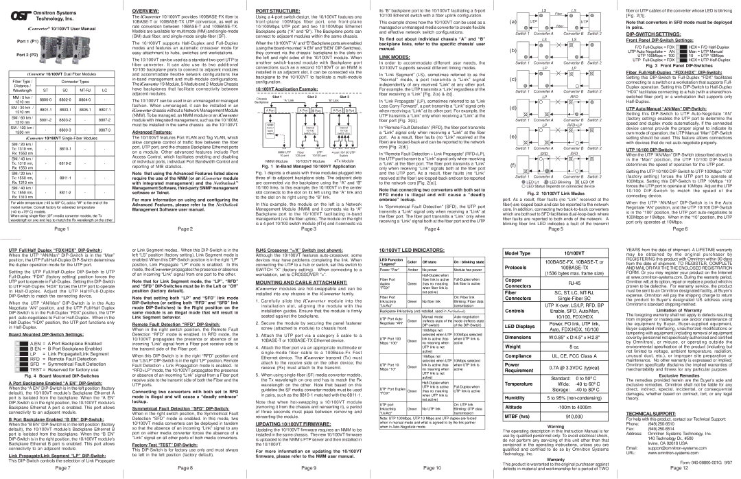
LINK MODES:
In order to accommodate different user needs, the 10/100VT supports several different linking modes.
In “Link Segment” (LS), sometimes referred to as the “Normal” mode, a port transmits a “Link” signal independently of any received “Link” at any other port. For example, the UTP transmits a “Link” regardless of the fiber receiving a “Link” [Fig. 2(a) & (b)].
In “Link Propagate” (LP), sometimes referred to as “Link Loss Carry Forward”, a port transmits a “Link” signal only when receiving a “Link” at its other port. For example, the UTP transmits a “Link” only when receiving a “Link” at the fiber port [Fig. 2(c)].
In “Remote Fault Detection” (RFD), the fiber port transmits a “Link” signal only when receiving a “Link” at the fiber port. As a result, fiber faults (no “Link” received at the fiber) are
In “Remote Fault Detection + Link Propagate” (RFD+LP), the UTP port transmits a “Link” signal only when receiving a “Link” at the fiber port. The fiber port transmits a “Link” only when receiving “Link” signals both at the fiber port and the UTP port. As a result, fiber faults (no “Link” received at the fiber) are
Note that connecting two converters with both set to RFD mode is illegal and will cause a “deadly embrace” lockup.
In “Symmetrical Fault Detection” (SFD), the UTP port transmits a “Link” signal only when receiving a “Link” at the fiber port. The fiber port transmits a “Link” only when receiving a “Link” signal both at the fiber port and the UTP
Page 4
10/100VT LED INDICATORS:
LED Function | Color | Off state | On / blinking state | |
"Legend" | ||||
|
|
| ||
Power "Pwr" | Amber | No power | Module has power | |
|
| |||
Fiber Port |
| fiber link is active | ||
duplex | Green | (has no meaning | link fiber is active | |
"FDX" |
| when fiber link is |
| |
|
| not active) |
| |
Fiber Port |
|
| On: Fiber link | |
link/activity | Green | No fiber link | Blinking: Fiber data | |
"Lk/Act" |
|
| transmission | |
Backplane link/activity (not installed, used in NetOutlook) | ||||
UTP Port Auto- |
| Manual mode | ||
Green | (reflects state of the | mode (reflects state | ||
Negotiate "AN" | ||||
| of the | |||
|
| |||
|
| 100Mbps not | 100Mbps selected | |
|
| selected when UTP | ||
UTP Port 100 | Green | link is active (has | when UTP link is | |
Mbps "100" | no meaning when | active | ||
| ||||
|
| UTP link is not |
| |
|
| active) |
| |
|
| 10Mbps not | 10Mbps selected | |
|
| selected when UTP | ||
UTP Port 10 | Green | link is active (has | when UTP link is | |
Mbps "10" | no meaning when | active | ||
| ||||
|
| UTP link is not |
| |
|
| active) |
| |
|
| |||
UTP Port Duplex |
| UTP link is active | ||
Green | (has no meaning | UTP link is active | ||
"FDX" |
| when UTP link is |
| |
|
|
| ||
|
| not active) |
| |
UTP port |
|
| On: UTP link | |
link/activity | Green | No UTP link | Blinking: UTP data | |
"Lk/Act" |
|
| transmission | |
Note: UTP 100Mbps, UTP 10 Mbps and UTP duplex are forced | ||||
when in manual mode and what is agreed to by the link partner | ||||
when in |
| |||
Page 10
LS | LS |
| Fiber |
(a) | UTP |
|
| UTP | |
|
|
| Fiber |
|
|
Switch 1 | Converter A | Converter B | Switch 2 | ||
|
| LS | LS |
|
|
(b) |
|
|
|
|
|
Switch 1 | Converter A | Converter B | Switch 2 | ||
|
| LP | LP |
|
|
(c) |
|
|
|
|
|
Switch 1 | Converter A | Converter B | Switch 2 | ||
|
| LP | RFD |
|
|
(d) |
|
|
|
|
|
Switch 1 | Converter A | Converter B | Switch 2 | ||
|
| LP | RFD+LP |
| |
(e) |
|
|
|
|
|
Switch 1 | Converter A | Converter B | Switch 2 | ||
|
| SFD | SFD |
|
|
(f) |
|
|
|
|
|
Switch 1 | Converter A | Converter B | Switch 2 | ||
LED Lit | LED Blinking | LED Off | |||
![]() LED Status depends on connected device
LED Status depends on connected device
Fig. 2 10/100VT Link Modes
port. As a result, fiber faults (no “Link” received at the fiber) are looped back and can be reported to the network core. In addition, connecting two
| Page 5 |
| |
|
| ||
Model Type | 10/100VT | ||
|
| ||
Protocols | |||
| (1536 bytes max. frame size) | ||
Copper | |||
Connectors | |||
|
| ||
Fiber | SC, ST, LC, | ||
Connectors | |||
Controls | UTP | ||
Enable, SFD, Auto/Man, | |||
| 10/100, FDX/HDX | ||
LED Displays | Power, FO link, UTP link, | ||
Auto, FDX/HDX, 10/100 | |||
| |||
Dimensions | W:0.85" x D:4.5" x H:2.8" | ||
|
| ||
Weight | 8 oz. | ||
|
| ||
Compliance | UL, CE, FCC Class A | ||
|
|
| |
Power | 0.7A @ 3.3VDC (typical) | ||
Requirement | |||
|
| ||
Temperature | Standard: | 0 to 50º C | |
Wide: | |||
| Storage: | ||
Humidity | 5 to 95% | ||
|
| ||
Altitude | |||
|
| ||
MTBF (hrs) | 910,000 | ||
|
|
| |
Warning
The operating description in this Instruction Manual is for use by qualified personnel only. To avoid electrical shock, do not perform any servicing of this unit other than that contained in the operating instructions, unless you are qualified and certified to do so by Omnitron Systems Technology, Inc.
Warranty
This product is warranted to the original purchaser against defects in material and workmanship for a period of TWO
fiber or UTP cables of the converter whose LED is blinking [Fig. 2(f)].
Note that converters in SFD mode must be deployed in pairs.
DIP-SWITCH SETTINGS:
Front Panel DIP-Switch Settings:
Fig. 3 Front Panel DIP-Switches
Fiber Full/Half-Duplex “FDX/HDX” DIP-Switch:
Setting this
UTP Auto/Manual “AN/Man” DIP-Switch:
Setting this
UTP 10/100 DIP-Switch:
When the UTP “AN/Man”
Setting the UTP 10/100
When the UTP “AN/Man”
Page 6
YEARS from the date of shipment. A LIFETIME warranty may be obtained by the original purchaser by REGISTERING this product with Omnitron within 90 days from the date of shipment. TO REGISTER, COMPLETE AND MAIL OR FAX THE THE ENCLOSED REGISTRATION FORM. Or you may register your product on the Internet at
Limitation of Warranty
The foregoing warranty shall not apply to defects resulting from improper or inadequate use and/or maintenance of the equipment by Buyer,
Exclusive Remedies
The remedies provided herein are the Buyer’s sole and exclusive remedies. Omnitron shall not be liable for any direct, indirect, special, incidental, or consequential damages, whether based on contract, tort, or any legal theory.
TECHNICALSUPPORT:
For help with this product, contact our Technical Support:
Phone: | (949) |
Fax: | (949) |
Address: | Omnitron Systems Technology, Inc. |
| 140 Technology Dr., #500 |
| Irvine, CA 92618 USA |
Email: | |
URL: | |
| Form: |
| Page 12 |