Channel Port (Left and Right)
The Channel Ports transmit and receive signals on a specific CWDM wavelength. The Channel Ports are multiplexed on and demultiplexed from the Common Ports. As shown in Figure 3 and 4, a
|
|
| CWDM/X |
|
|
|
|
|
|
|
|
| CWDM/X | |||||||||
1 |
|
|
|
|
|
|
|
|
| CWDM / AD |
|
|
|
|
|
|
| 1 | ||||
|
|
|
|
|
|
|
|
|
|
|
|
|
| |||||||||
2 |
|
|
|
|
|
|
|
|
|
|
|
|
|
|
|
|
|
|
|
|
| 2 |
|
|
|
|
|
|
|
| 2 - 4 |
|
|
|
|
|
| ||||||||
|
|
|
|
|
|
|
|
|
|
| ||||||||||||
3 |
|
|
|
|
|
|
|
|
|
|
|
|
|
|
|
|
|
|
|
|
| 3 |
|
|
|
|
|
|
|
|
|
|
|
|
|
|
|
|
|
|
|
|
| ||
|
|
|
|
|
|
|
|
|
|
|
|
|
|
|
|
|
|
| ||||
4 |
|
|
|
|
|
|
|
|
|
|
|
|
|
|
|
|
|
|
|
|
| 4 |
|
|
|
|
|
|
|
|
|
|
|
|
|
|
|
|
|
|
| ||||
|
|
|
|
|
|
|
|
|
|
|
|
|
|
|
|
|
|
|
|
|
|
|
|
|
|
|
|
|
|
|
|
|
|
|
|
|
|
|
|
|
|
|
|
|
|
1 1
(Left) (Right)
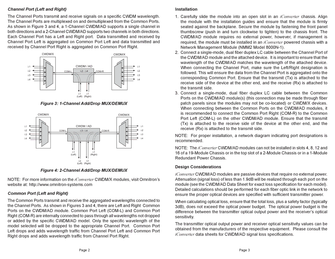
Figure 3: 1-Channel Add/Drop MUX/DEMUX
Installation
1. Carefully slide the module into an open slot in an iConverter chassis. Align |
the module with the installation guides and ensure that the module is firmly |
seated against the backplane. Secure the module by fastening the front panel |
thumbscrew (push in and turn clockwise to tighten) to the chassis front. The |
CWDM/AD module requires no external power, however, if management is |
required, the module must be installed in an iConverter powered chassis with a |
Network Management Module (NMM2 Model |
2. Connect a |
the CWDM/AD module and the attached device. It is important to ensure that the |
wavelength of the CWDM/AD matches the wavelength of the attached device. |
When connecting the Channel Port, make sure the Left/Right designation is |
followed. This will ensure the data from the Channel Port is aggregated onto the |
corresponding Common Port. Ensure that the transmit (Tx) is attached to the |
receive side of the device at the other end, and the receive (Rx) is attached to |
the transmit side. |
3. Connect a |
Ports on the CWDM/AD module(s) (this connection may be made through fiber |
patch panels since the modules may not be |
When connecting between the Common Ports on the CWDM/AD modules, it |
is recommended to connect the Common Port Right |
CWDM/X
1 2 3 4
CWDM/X
CWDM / AD
3 - 4 |
|
|
|
|
|
|
|
|
|
|
|
|
|
|
|
|
|
|
|
|
1 |
|
|
|
| 1 | ||||
(Left) |
|
|
|
| (Right) | ||||
|
|
|
|
|
|
|
|
|
|
|
| 2 | 2 | ||||||
|
| (Left) | (Right) | ||||||
1 2 3 4
Port Left |
(Tx) is attached to the receive side of the device at the other end, and the |
receive (Rx) is attached to the transmit side. |
NOTE: For proper installation, a network diagram indicating port designations is recommended.
NOTE: The iConverter CWDM/AD modules can not be installed in slots 4, 8, 12 and 16 of a
Design Considerations
Figure 4: 2-Channel Add/Drop MUX/DEMUX
NOTE: For more information on the iConverter CWDM/X modules, visit Omnitron’s
website at:
Common Port (Left and Right)
The Common Ports transmit and receive the aggregated wavelengths connected to the Channel Ports. As shown in Figures 3 and 4, there are Left and Right Common Ports on the CWDM/AD module. Common Port Left
iConverter CWDM/AD modules are passive devices that require no external power. Attenuation (signal loss) of less than 1.9dB will be realized through each port on the module (see the CWDM/AD Data Sheet for exact loss specification for each model). Detailed calculations should be performed for each fiber optic link in the network to ensure the proper optical devices are specified with sufficient transmitter power.
When calculating optical loss, ensure that the total loss, plus a safety factor (typically 3dB), does not exceed the optical power budget. The optical power budget is the difference between the transmitter optical output power and the receiver’s optical sensitivity.
The transmitter optical output power and receiver optical sensitivity values can be obtained from the manufacturers of the respective equipment. Please consult the
iConverter data sheets for CWDM/AD signal loss specifications.
Page 2 | Page 3 |