FlexPoint™ GX/T
10/100/1000 UTP to 100/1000X
Ethernet Media Converter
User Manual
DESCRIPTION:
The FlexPoint GX/T is a
Both the fiber port and the UTP port support auto- negotiation, an IEEE standard which defines how all the communicating devices automatically perform their configuration functions.
The
Page 1
setting the
Loopback “Off/On”
Setting this
Link Modes:
See the following table for configuring link modes:
SW9 | SW10 | Result | |
"LS/LP" | "RFD/Normal" |
| |
LS | Normal | Enables Link Segment mode (LS). | |
LP | Normal | Enables Link Propagate mode (LP). | |
LS | RFD | Enables Remote Fault Detection mode plus | |
Link Segment mode (RFD+LS). | |||
|
| ||
LP | RFD | Enables Remote Fault Detection mode plus | |
Link Propagation mode (RFD+LP). | |||
|
|
NOTE: RFD is only available when the fiber port is operating in manual mode.
REMOTE FAULT
Each port will generate an “IEEE remote_fault indicator” when the incoming signal to the port is lost. When a port is configured for
When the fiber port is operating in
Fiber Type | Distance |
| Connector Type |
| ||
|
|
|
|
| ||
|
| ST |
| SC |
| SFP |
SFP | - | - |
| - |
| |
MM | 220 / 550m 1 |
|
| - | ||
SM | 12km |
|
| - | ||
SM | 34km | - |
|
| - | |
SM | 80km | - |
|
| - | |
SM | 110km | - |
|
| - | |
SM | 140km | - |
|
| - | |
20km | - |
|
| - | ||
1310/1550 |
|
| ||||
|
|
|
|
|
| |
20km | - |
|
| - | ||
1550/1310 |
|
| ||||
|
|
|
|
|
| |
40km | - |
|
| - | ||
1310/1550 |
|
| ||||
|
|
|
|
|
| |
40km | - |
|
| - | ||
1550/1310 |
|
| ||||
|
|
|
|
|
| |
Power Adapter Kits (-x):
For other power and fiber configurations, contact the factory.
1 62.5/125µm, 100/140µm multimode fiber up to 220m, 50/125µm multimode fiber up to 550m. Refer to the fiber cable manufacturer for multimode distance specifications.
POWER ADAPTER NOTICE:
1.This product should only be used with Omnitron Supplied Power Unit model numbers
2.When used in a standalone configuration, this product must be used with a Listed Direct
NOTE: If mounting with a safety ground attachment, use the safety ground screw at the rear of the unit.
NOTE: Remove safety ground screw when installing the module in the
Page 2
UTP MODES
SW3 | SW4 | SW5 | SW6 | UTP Mode of Operation |
AN/MAN | 10/100/ | 10/100 | FDx/HDx |
|
| 1000 |
|
|
|
AN | 1000 | NA | FDX | Configured for Auto Negotiation. |
|
|
|
| (1000F, 1000H, 100F, 100H, 10F, |
|
|
|
| 10H) |
AN | 1000 | NA | HDX | Configured for Auto Negotiation. |
|
|
|
| (1000H, 100F, 100H, 10F, 10H) |
AN | 100 | FDX | Configured for Auto Negotiation. | |
|
|
|
| (100F, 100H, 10F, 10H) |
AN | 100 | HDX | Configured for Auto Negotiation. | |
|
|
|
| (100H, 10F, 10H) |
AN | 10 | FDX | Configured for Auto Negotiation. | |
|
|
|
| (10F, 10H) |
AN | 10 | HDX | Configured for Auto Negotiation. | |
|
|
|
| (10H) |
MAN | 1000 | NA | FDX | Configured for Auto Negotiation. |
|
|
|
| (1000F) |
|
|
|
| When the port is set to 1000, it is |
|
|
|
| always in AN mode. |
MAN | 1000 | NA | HDX | Configured for Auto Negotiation. |
|
|
|
| (1000H) |
|
|
|
| When the port is set to 1000, it is |
|
|
|
| always in AN mode. |
MAN | 100 | FDX | Port forced to 100 FDX | |
MAN | 100 | HDX | Port forced to 100 HDX | |
MAN | 10 | FDX | Port forced to 10 FDX | |
MAN | 10 | HDX | Port forced to 10 HDX |
When the module is configured for
it with the
WARNING!
Before inserting the Power Adapter, verify that the power on the unit is appropriate
for your AC line voltage source.
INSTALLATION PROCEDURE
1.) Configure the appropriate FlexPoint GX/T
2.) Connect the UTP port via a Category 5 or better cable to a
3.) When using fixed fiber port models, connect the appropriate multimode or
4.) When using a GX/T SFP model, insert the SFP Fiber transceiver into the Port 1 SFP receptacle on the GX/T.
NOTE: The release latch of the SFP Fiber transceiver must be in the closed (up) position before insertion.
LOOPBACK
The FlexPoint GX/T has the capability to provide loopback to aid in installation and maintenance. A
|
|
| Page 3 |
|
LED INDICATORS |
| |||
|
|
|
|
|
LED Function |
| Color | Off State | On / Blinking State |
"Legend" |
|
| ||
|
|
|
| |
|
|
|
|
|
Power / Test |
|
|
| On: Module has power |
| Green | No power | Blinking: Module in loopback | |
"Power" |
| |||
|
|
| mode | |
|
|
|
| |
F/O AN |
| Green | Port configured for | On: Fiber port configured for AN |
| manual negotiation | Blinking: Fiber port configured for | ||
|
|
|
| AN but in manual mode |
|
|
|
| On: Fiber port linked at 100Mbps |
F/O Speed 100* |
|
| Not connected at | Blinking (10Hz): Link activity at |
| Green | 100Mbps | ||
| 100Mbps |
| ||
|
| Blinking (1Hz): Signal detected | ||
|
|
|
| |
|
|
|
| but port unable to establish a link |
|
|
|
| On: Fiber port linked at 1000Mbps |
|
|
|
| Blinking (10Hz): Link activity at |
F/O Speed 1000 |
|
| Not connected at | 1000Mbps |
| Green |
| ||
| 1000Mbps | Blinking (1Hz): Signal detected | ||
|
| |||
|
|
|
| but port unable to establish a link |
|
|
|
| Pattern Blinking: AN remote Fault |
|
|
|
| bit detected |
UTP Duplex |
| Green | On: UTP port in | |
|
| |||
|
|
|
| |
UTP AN |
| Green | Port configured for | On: UTP port configured for AN |
| manual negotiation | Blinking: UTP port configured for | ||
|
|
|
| AN but in manual mode |
UTP Speed 100 |
| Green | Not connected at | On: UTP port linked at 100Mbps |
| 100Mbps | Blinking (10Hz): Link activity | ||
|
| |||
|
|
|
|
|
UTP Speed 1000 |
| Green | Not connected at | On: UTP port linked at 1000Mbps |
| 1000Mbps | Blinking (10Hz): Link activity | ||
|
| |||
|
|
|
|
|
UTP Speed 10 |
|
|
| On: UTP port linked at 10Mbps |
|
|
| Blinking (10Hz): Link activity | |
| Green | Not connected at | ||
|
| |||
+ |
| 10Mbps | Pattern Blinking: (1Hz): Detecting | |
|
| |||
|
|
| ||
|
|
| "remote_fault" (AN) on UTP port | |
|
|
|
| |
"UTP |
|
|
|
|
+ |
|
|
| Blinking (1Hz): Unable to establish |
| Green | - | ||
| AN link on the UTP port | |||
+ |
|
|
| |
|
|
|
| |
|
|
|
| |
|
|
|
|
|
*SFP models only |
|
|
| |
| FlexPoint GX/T |
| |
RX | TX | RX | TX |
UTP | Fiber | UTP | Fiber |
TX | RX | TX | RX |
Normal Mode | Loopback Mode |
Figure 1: Loopback Mode
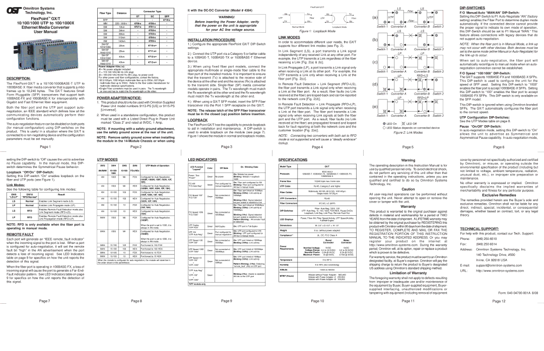
LINK MODES
In order to accommodate different user needs, the GX/T supports four different link modes (see Fig. 2).
In Link Segment (LS), a port transmits a Link signal independently of any received Link at any other port. For example, the UTP transmits a Link regardless of the fiber receiving a Link [Fig. 2(a) & (b)].
In Link Propagate (LP), a port transmits a Link signal only when receiving a Link at its other port. For example, the UTP transmits a Link only when receiving a Link at the fiber port [Fig. 2(c)].
In Remote Fault Detection + Link Segment (RFD+LS), the fiber port transmits a Link signal only when receiving a Link at the fiber port. As a result, fiber faults (no Link received at the fiber) are
In Remote Fault Detection + Link Propagate (RFD+LP), the UTP port transmits a Link signal only when receiving a Link at the fiber port. The fiber port transmits a Link signal only when receiving Link signals at both the fiber port and the UTP port. As a result, fiber faults (no Link received at the fiber) are propagated forward and looped back for fault reporting at both the network core and the customer location [Fig. 2(e)].
NOTE: Connecting two converters with both set to RFD mode is not supported and will cause a “deadly embrace” lockup.
| Page 4 |
| ||
SPECIFICATIONS |
|
| ||
|
|
|
| |
Model Type |
| GX/T |
| |
|
|
|
| |
Protocols |
| IEEE 802.3 |
| |
|
|
| ||
|
| |||
Frame Size | 10,240 byte max. frame size | |||
|
| |||
UTP Cable | ||||
|
| |||
Fiber Cables | Multimode: 50/125, 62.5/125, 100/140µm | |||
| ||||
|
| |||
|
|
|
| |
UTP Connectors |
|
| ||
|
|
| ||
Fiber Connectors | ST, SC, LC (SFP) |
| ||
|
| |||
| Fiber: | |||
UTP: | ||||
| Loopback, Link Seg, Link Prop, Remote Fault Det. | |||
|
| |||
LED Displays | Power, Fiber AN, Fiber Speed/Activity, UTP Speed/Activity, | |||
| ||||
|
| |||
|
| |||
Dimensions | W: 3.0" x D: 4.0" x H: 1.0" | |||
|
| |||
Weight | 6 oz. (without power adapter) | |||
|
|
| ||
Compliance** | UL, CE, FCC Class A |
| ||
|
|
|
| |
|
| Barrel | Molex | |
|
| Connector | Connector | |
Power | Nominal Voltage: | 9VDC | 5VDC | |
Requirements | ||||
Voltage Range: 5.0 to 32.0VDC | 5.0 to 32.0VDC | |||
| ||||
| Nominal Power: | 0.3A @ 9VDC | 0.5A @ 5VDC | |
| Maximum Power: | 1A @ 9VDC | 0.75A @ 5VDC | |
|
|
|
| |
Temperature |
| 0 to 50o C |
| |
|
| |||
Humidity | 5 to 95% | |||
|
|
| ||
Altitude |
| |||
|
| |||
MTBF (Hours) | Module without Power Adapter: 900,000 | |||
Module with Power Adapter | ||||
| ||||
| Module with Power Adapter | 100,000 | ||
|
|
|
| |
LS | LS |
| Fiber |
(a) | UTP | UTP | |
|
| Fiber |
|
Switch 1 | Converter A | Converter B | Switch 2 |
| LS | LS |
|
(b) |
|
|
|
Switch 1 | Converter A | Converter B | Switch 2 |
| LP | LP |
|
(c) |
|
|
|
Switch 1 | Converter A | Converter B | Switch 2 |
| LP | RFD+LS |
|
(d) |
|
|
|
Switch 1 | Converter A | Converter B | Switch 2 |
| LP | RFD+LP |
|
(e) |
|
|
|
Switch 1 | Converter A | Converter B | Switch 2 |
LED On | LED Off |
| |
![]() LED Status depends on connected device
LED Status depends on connected device
Figure 2: Link Modes
Page 5
Warning
The operating description in this Instruction Manual is for use by qualified personnel only. To avoid electrical shock, do not perform any servicing of this unit other than that contained in the operating instructions, unless you are qualified and certified to do so by Omnitron Systems Technology, Inc.
Caution
All
Warranty
This product is warranted to the original purchaser against defects in material and workmanship for a period of TWO YEARS from the date of shipment. ALIFETIME warranty may be obtained by the original purchaser by REGISTERING this product with Omnitron within 90 days from the date of shipment.
TO REGISTER, COMPLETE AND MAIL OR FAX THE REGISTRATION PORTION OF THIS INSTRUCTION MANUAL TO THE INDICATED ADDRESS. Or you may register your product on the internet at
For warranty service, the product must be sent to an Omnitron designated facility, at Buyer’s expense. Omnitron will pay the shipping charge to return the product to Buyer’s designated US address using Omnitron’s standard shipping method.
Limitation of Warranty
The foregoing warranty shall not apply to defects resulting from improper or inadequate use and/or maintenance of the equipment by Buyer,
DIP-SWITCHES
F/O Manual/Auto “MAN/AN” DIP-Switch:
Setting this
NOTE: When the fiber port is in Manual Mode, a
When set to
F/O Speed “100/1000” DIP-Switch:
The GX/T supports
This
UTP Configuration
See the UTP Modes table on page 8.
Pause “On/Off” DIP-Switch:
In
Page 6
cover by personnel not specifically authorized and certified by Omnitron), or misuse, or operating outside the environmental specification of the product (including but not limited to voltage, ambient temperature, radiation, unusual dust, etc.), or improper site preparation or maintenance.
No other warranty is expressed or implied. Omnitron specifically disclaims the implied warranties of merchantability and fitness for any particular purpose.
Exclusive Remedies
The remedies provided herein are the Buyer’s sole and exclusive remedies. Omnitron shall not be liable for any direct, indirect, special, incidental, or consequential damages, whether based on contract, tort, or any legal theory.
TECHNICAL SUPPORT:
For help with this product, contact our Tech. Support:
Phone: | (949) |
Fax: | (949) |
Address: Omnitron Systems Technology, Inc. | |
| 140 Technology Drive, #500 |
| Irvine, CA 92618 USA |
URL: | |
Form:
Page 7 | Page 8 | Page 9 | Page 10 | Page 11 | Page 12 |