iConverter® RS422/485
Serial RS-422 and RS-485 to
Fiber Media Converter User Manual
Port 1 (P1)
Port 2 (P2)
iConverter RS422/485 DB-9 Models
Fiber Type / |
| Fiber Connector Types | ||||
Dual Fiber [DF] or | Distance | |||||
|
|
|
| |||
ST | SC |
| LC | |||
| ||||||
Wavelength |
| |||||
|
|
|
|
| ||
MM/DF/1310nm | 5km | |||||
SM/DF/1310nm | 30km | |||||
SM/DF/1310nm | 60km | - | ||||
SM/DF/1550nm | 120km | - | - | |||
iConverter RS422/485 |
| |||||
SM/SF/ | 20km | - | - | - | ||
Tx 1310/Rx 1550 | ||||||
|
|
|
|
| ||
SM/SF | 20km | - | - | - | ||
Tx 1550/Rx 1310 | ||||||
|
|
|
|
| ||
SM/SF/ | 40km | - | - | - | ||
Tx 1310/Rx 1550 | ||||||
|
|
|
|
| ||
SM/SF | 40km | - | - | - | ||
Tx 1550/Rx 1310 | ||||||
|
|
|
|
| ||
For wide temperature
When using
When ordering module with terminal block serial port, append 'T' before the dash
Page 1
“NORM” position (factory default), the RS422/485 operates in a
When this
Board-Mounted Bank 2 DIP-Switches:
Note that Bank 2
Fig. 5 Bank 2 DIP-Switch Description
Bank2 SW1 and SW2: Head Termination “HEAD” DIP-Switches:
Bank 2 Head Termination “HEAD”
Note that both of the Head Termination “HEAD”
Bank2 SW3 through SW6: Mid Termination “MID/H-T” DIP-Switches:
Bank 2 Mid Termination
Page 7
OVERVIEW:
The Omnitron iConverter RS422/485 is a manageable serial
The RS422/485 is available with a
The RS422/485 automatically detects the signal baud rate of the connected
A
The RS422/485 is designed to work in any iConverter chassis. When installed in a
Note that software control for remote configuration of the RS422/485 requires a
Page 2
providing parallel terminations. When these
Note that all of the Mid Termination
Termination Table
| ||||||
Switch No. | Head | Tail | Mid | Head | Tail | Mid |
1 | OFF | OFF | OFF | ON | OFF | OFF |
2 | OFF | OFF | OFF | ON | OFF | OFF |
3 | ON | ON | OFF | ON | ON | OFF |
4 | ON | ON | OFF | ON | ON | OFF |
5 | ON | ON | OFF | ON | ON | OFF |
6 | ON | ON | OFF | ON | ON | OFF |
| Fiber | ||
` | RS422/485 | RS422/485 |
|
|
| ||
Master | “TAIL” | “HEAD” | Slave |
“HEAD” |
|
| “TAIL” |
Fig. 6a Head and Tail Termination Application
Master | Slave | |
“HEAD” | ` | “TAIL” |
|
| |
| RS422/485 |
|
| “MID” |
|
| Fiber |
|
RS422/485
“HEAD”
Slave
“TAIL”
Fig. 6b Mid and Head Termination Application
Page 8
For more information on using and configuring the RS422/485 via software control, please refer to the NetOutlook™ Management Software user manual.
PORT STRUCTURE:
Front-Panel Ports:
The
Fig. 1a DB-9 Connector Pin-Out Assignment
Fig. 1b Terminal Block Pin-Out Assignment
PIN |
| |||||
Normal | ||||||
No. |
|
|
|
|
|
|
Signal | DTE |
| DCE | - | - | |
|
| |||||
1 | Ground | - |
| - | Reserved | Ground |
2 | RTS+ | OUT |
| IN | Reserved | Reserved |
3 | RTS- | OUT |
| IN | Reserved | Reserved |
4 | TXD+ | OUT |
| IN | TXD+ (IN) | DATA+ |
5 | TXD- | OUT |
| IN | TXD- (IN) | DATA |
6 | CTS+ | IN |
| OUT | Reserved | Reserved |
7 | CTS- | IN |
| OUT | Reserved | Reserved |
8 | RXD+ | IN |
| OUT | RXD+ (OUT) | Reserved |
9 | RXD- | IN |
| OUT | RXD- (OUT) | Reserved |
Page 3
MOUNTING AND CABLE ATTACHMENT:
iConverter modules are
1.After configuring the
2.Secure the module by fastening the panel thumb screw (attached to the module) to the chassis front.
3.Attach the serial ports via a
4.Attach the fiber port via an appropriate multimode or
5.When using
Page 9
DIP-SWITCH SETTINGS:
Front-Panel DIP-Switches
Fig. 2 Front-Panel DIP-Switches
SW1: Normal and Fiber Loop-Back “Norm - FLB” DIP-Switch:
When the Normal and Fiber
Note that the Fiber
Note that if both RS422/485 on the ends of a fiber segment are set to the “FLB” position during the
SW2: Serial “DCE - DTE” DIP-Switch:
When the “DCE - DTE”
Note that the “DCE - DTE”
Page 4
RS422/485 LED INDICATORS:
LED Function | Color | Off State | On States |
"Legend" |
|
|
|
Power "Pwr" | Amber | No Power | Module has power |
|
|
| Solid: Master mode Tx |
|
|
| pattern sent, but no Rx |
|
|
| received |
Fiber Loop- |
| Normal | 10 Hz (Blinking 10x per |
Green | second): Master mode, | ||
back Test "Tst" |
| Mode | Tx pattern sent, and Rx |
|
|
| pattern received |
|
|
| 1 Hz (Blinking once per |
|
|
| second): Slave mode, |
|
|
| Rx pattern received |
Fiber Link and |
| No Fiber | Solid: Fiber Link |
Green | Active | ||
Activities "Act" | Link | Blinking: Fiber Data | |
|
|
| Transmission |
"DTE" Mode | Green | DTE mode | DTE mode selected |
not selected | |||
"DCE" Mode | Green | DCE mode | DCE mode selected |
not selected | |||
Serial | Green | No serial | Serial data received |
Activities "Act" | data |
TECHNICAL SUPPORT:
For help with this product, contact our Technical Support:
Phone: | (949) |
Fax: | (949) |
Address: Omnitron Systems Technology, Inc. | |
| 140 Technology Dr., #500 |
| Irvine, CA 92618 USA |
URL: | |
Page 10
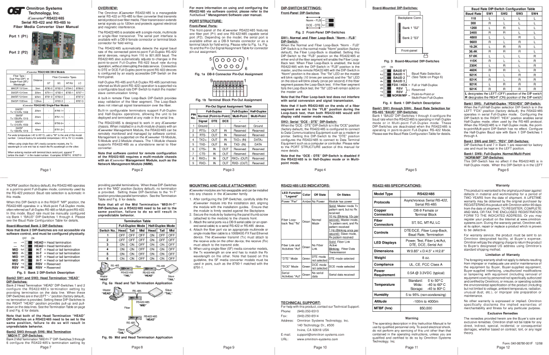
Fig. 3 Board-Mounted DIP-Switches
OFF | ON |
|
| ||
1 |
|
| BAUD 0 |
|
|
2 |
|
| BAUD 1 |
| Baud Rate Selection |
|
|
| |||
3 |
|
| BAUD 2 | = (See Table on Page 6) | |
|
| ||||
4 |
|
| BAUD 3 |
|
|
|
|
|
| ||
5 |
|
| FDX / HDX = | Full or | |
|
| ||||
6 |
|
| RSV | = | Reserved |
|
| ||||
7 |
|
| RSV | ||
|
| ||||
8 |
|
| NORM/MP = | ||
|
| ||||
|
|
|
|
|
|
|
|
|
|
| |
Fig. 4 Bank 1 DIP-Switch Description
Bank1 SW1 through SW4: Baud Rate Selection for RS-485 “BAUD” DIP-Switches:
Bank 1 “BAUD”
| Page 5 |
| |
RS422/485 SPECIFICATIONS: |
| ||
|
| ||
Model Type | RS422/485 | ||
|
| ||
Protocols | Asynchronous Serial | ||
Serial | |||
| |||
Copper | |||
Connectors | Terminal Block | ||
Fiber | ST, SC, | ||
Connectors | |||
|
| ||
Controls | DTE/DCE, Fiber | ||
Baud Rate, Termination | |||
| |||
LED Displays | Power, Test, Fiber Lnk/Act, | ||
DTE, DCE, Serial Act | |||
| |||
Dimensions | W:0.85" x D:4.5" x H:2.8" | ||
|
| ||
Weight | 8 oz. | ||
|
| ||
Compliance | UL, CE, FCC Class A | ||
|
|
| |
Power | 0.5A @ 3.3VDC (typical) | ||
Requirement | |||
|
| ||
Temperature | Standard: | 0 to 50º C | |
Wide: | |||
| Storage: | ||
Humidity | 5 to 95% | ||
|
| ||
Altitude | |||
|
| ||
MTBF (hrs) | 850,000 | ||
|
|
| |
Warning
The operating description in this Instruction Manual is for use by qualified personnel only. To avoid electrical shock, do not perform any servicing of this unit other than that contained in the operating instructions, unless you are qualified and certified to do so by Omnitron Systems Technology, Inc.
Page 11
Baud Rate
Baud Rate | SW1 | SW2 | SW3 | SW4 |
110 | L | L | L | L |
300 | R | L | L | L |
1200 | L | R | L | L |
2400 | R | R | L | L |
4800 | L | L | R | L |
9600 | R | L | R | L |
19.2K | L | R | R | L |
38.4K | R | R | R | L |
57.6K | L | L | L | R |
115K | R | L | L | R |
230K | L | R | L | R |
460K | R | R | L | R |
921K | L | L | R | R |
921K | R | L | R | R |
921K | L | R | R | R |
921K | R | R | R | R |
Ldesignates the LEFT (OFF) position of the
Bank1 SW5:
Bank1 SW6 and SW7: “RSV”
Bank1 SW8:
This
Page 6
Warranty
This product is warranted to the original purchaser against defects in material and workmanship for a period of TWO YEARS from the date of shipment. A LIFETIME warranty may be obtained by the original purchaser by REGISTERING this product with Omnitron within 90 days from the date of shipment. TO REGISTER, COMPLETE AND MAIL OR FAX THE ENCLOSED REGISTRATION FORM TO THE INDICATED ADDRESS. Or you may register your product on the Internet at www.omnitron- systems.com. During the warranty period, Omnitron will, at its option, repair or replace a product which is proven to be defective.
For warranty service, the product must be sent to an Omnitron designated facility, at Buyer’s expense. Omnitron will pay the shipping charge to return the product to Buyer’s designated US address using Omnitron’s standard shipping method.
Limitation of Warranty
The foregoing warranty shall not apply to defects resulting from improper or inadequate use and/or maintenance of the equipment by Buyer,
No other warranty is expressed or implied. Omnitron specifically disclaims the implied warranties of merchantability and fitness for any particular purpose.
Exclusive Remedies
The remedies provided herein are the Buyer’s sole and exclusive remedies. Omnitron shall not be liable for any direct, indirect, special, incidental, or consequential damages, whether based on contract, tort, or any legal theory.
Form:
Page 12