iConverter® T3/E3 User Manual
T3/E3 MODEL NUMBER REFERENCE CHART:
iConverter T3/E3 Coax Dual Fiber Modules
Fiber Type | Distance |
| Connector Type |
| |||
|
|
|
|
| |||
ST | SC | LC | SFP | ||||
|
| ||||||
|
|
|
|
|
|
| |
- | - | - | - | - | - | ||
MM | 5 km | - | - | ||||
SM | 30 km | - | |||||
SM | 60 km | - | - | ||||
FRONT PANEL | “CLB” | |||||||||||||||
The following | This | |||||||||||||||
These switches provide data path control (normal operation and loop- | Loopback Mode (Figure 4) and the “CLB” LED is turned ON. When in this | |||||||||||||||
backs) and test patterns (all 1’s) that assist in installation and fault isolation. | mode, data received at the | |||||||||||||||
|
|
|
|
|
|
|
| |||||||||
|
|
|
|
|
|
|
| out both | ||||||||
|
|
|
|
|
|
|
| position, the unit resumes normal operation. | ||||||||
|
|
|
|
|
|
|
|
|
|
|
|
|
|
|
|
|
|
|
|
|
|
|
|
|
|
|
|
|
|
|
|
|
|
|
|
|
|
|
|
|
|
|
|
|
|
|
|
|
|
|
|
|
|
|
|
|
|
|
|
|
|
|
|
|
|
|
|
|
|
|
|
|
|
|
|
|
|
|
|
|
|
|
|
|
|
|
|
|
|
|
|
|
|
|
|
|
|
|
|
|
|
“FAIS” Force AIS to Fiber (Force 1’s to Fiber):
When the “FAIS”
“CAIS” Force AIS to Coax (Force 1’s to Coax):
When the “CAIS”
OVERVIEW:
The iConverter T3/E3 managed media converter is a member of the modular iConverter product family. The T3/E3 provides standard T3 (B3ZS line protocol, 44.763Mbps) or E3 (HDB3 line protocol, 34.368Mbps) coax to fiber conversion and can be used by telco service providers and enterprise users to connect devices such as PBXs, multiplexers, routers and video servers via multimode (MM),
Designed to extend the standard T3/E3 Coax network distances over fiber, this converter provides protection from environmental noise and effectively increases
The T3/E3 module can be used in any of the iConverter chassis such as the
The T3/E3 can be used in a managed or unmanaged fashion. When unmanaged, it can be installed in an iConverter chassis without a Network Management Module (NMM). To be managed, a NMM module must be installed in the same chassis as the T3/E3 module. To read about specific management functionality, refer to the NetOutlook™ user manual T3/E3 section.
This User Manual covers the models listed in the following table.
Page 1
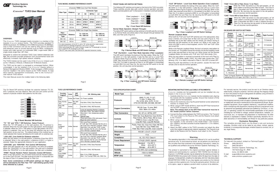
The On Board
Fig. 6 Board Mounted DIP-Switches “T3” “E3” and “STS-1” DIP-Switches - Select Protocol:
When the “T3”
“<225/>225” Coax Build-Out Distance selection:
When this
“CEN/CDIS” and “FEN/FDIS” Port Control DIP-Switches:
When both
“PRBS” Pseudo Random Pattern Generator Control
Note: Some combinations of
Page 6
SM | 120 km | - |
| - |
| - |
|
|
|
|
| ||
| iConverter T3/E3 Coax |
| ||||
Fiber / |
|
| Tx: 1310 nm, |
| Tx: 1550 nm, |
|
Connector | Distance |
|
|
| ||
| Rx: 1550 nm |
| Rx: 1310 nm |
| ||
Type |
|
|
|
| ||
|
|
|
|
|
| |
SM / SC | 20 km |
|
|
| ||
|
|
|
|
|
|
|
SM / SC | 40 km |
|
|
|
|
|
For wide temperature
When using
*See SFP data sheet under Fast Ethernet for supported transceiver models.
|
|
| Page 2 | |
T3/E3 LED REFERENCE CHART: | ||||
|
|
|
| |
Function | Color | OFF | ON / Blinking state | |
"Legend" | State | |||
|
| |||
Power | Amber | No Power | On: Power available | |
"Pwr" | ||||
|
|
| ||
Fiber Activity | Green | No valid | Fast blink (10Hz): Data Received | |
"Act" | data | |||
Fiber AIS | Amber | Fast blink (10Hz): AIS Received. | ||
"AIS" | ||||
|
|
| ||
|
|
| Local unit asserting Remote Loopback: | |
Fiber Test |
| No Test | Fast blink (10Hz): Test pattern received. | |
| Slow blink (1 Hz): Unexpected pattern | |||
detected | Amber | Data | received. | |
"TST" |
| Received | Special Case: | |
|
|
| Three quick blinks (2Hz) and pause (1sec.): | |
|
|
| Illegal | |
|
|
| ON: Local Fiber Loopback. | |
Fiber |
|
| If "CLB" also "ON" indicates that the unit is | |
|
| the Local Unit in Remote Loopback Mode. | ||
Loopback | Amber | Normal | ||
Slow blink (1Hz) and also "CLB" in slow | ||||
"FLB" |
|
| ||
|
| blink: indicates that the unit is the Remote | ||
|
|
| ||
|
|
| Unit in Remote Loopback Mode. | |
|
|
| ON: Local Coax Loopback. | |
Coax |
|
| If "FLB" also "ON" indicates that the unit is | |
|
| the Local Unit in Remote Loopback Mode. | ||
Loopback | Amber | Normal | ||
Slow blink (1Hz) and also "FLB" in slow | ||||
"CLB" |
|
| ||
|
| blink: indicates that the unit is the Remote | ||
|
|
| ||
|
|
| Unit in Remote Loopback Mode. | |
Coax Activity | Green | No valid | Fast blink (10Hz): Data Received | |
"ACT" |
| data |
| |
Coax AIS |
|
|
| |
detected | Amber | Fast blink (10Hz): AIS Received. | ||
"AIS" |
|
|
| |
Coax PRBS |
|
| Blink 10 Hz: PRBS Received. | |
detected | Amber | |||
Blink 1 Hz: Forcing PRBS onto | ||||
"PRBS" |
|
| ||
|
|
| ||
|
|
| Page 7 | |
Fig. 1 Front Panel DIP-Switches
Normal Mode Operation (Straight Through):
The default
Fig. 2 Normal Mode and DIP-Switch Settings
“FLB” Dip-Switch - Local Fiber Mode Operation (Fiber Loopback):
This
Fig. 3 Fiber Loopback and DIP-Switch Settings
Page 3
T3/E3 SPECIFICATION CHART:
Model Type | T3/E3 | ||
| ANSI: T1.102, T1.107, | ||
Protocols | T1.404, | ||
ITU: G.703, (E3), G.751, O.151 | |||
| |||
| ETSI: EN 300 689, 300 686, 300 687 | ||
|
| ||
Copper Connectors | |||
DS3: 380m, E3: 440m | |||
| |||
|
| ||
Fiber Connectors | SC, ST, LC, | ||
| T3/E3 Sel, Coax | ||
Controls | Fiber En/Dis, AIS to Fiber, AIS to Coax, | ||
PRBS to Coax, | |||
| |||
| |||
LED Displays | Power, Fiber Act, Coax Act, Fiber AIS Det, | ||
Coax AIS Det, Coax PRBS Det, | |||
| Fiber Test, Fiber | ||
|
| ||
Dimensions | W:0.85" x D:4.5" x H:2.8" | ||
Weight |
| 8 oz. | |
Compliance | UL, CE, FCC Class A | ||
Power Requirement | 0.7A @ 3.3VDC (typical) | ||
Temperature | Standard: | 0 to 50º C | |
Wide: | |||
| Storage: | ||
Humidity | 5 to 95% | ||
Altitude | |||
MTBF (hrs) | 510,000 | ||
|
|
| |
Page 8
Fig. 4 Coax Loopback and DIP-Switch Settings Remote Loopback Mode:
When both the “FLB” and “CLB”
While in the Remote Loopback Mode, the local unit sends a test pattern to the remote unit. This pattern forces the remote unit into the loopback mode and is also returned back to the local unit. When forced into the Remote Loopback Mode, the remote unit’s “FLB” and “CLB” blink slowly (1Hz).
When the test pattern is received successfully at the local unit’s
Returning both
Fig. 5 Remote Loopback and DIP-Switch Settings
Page 4
MOUNTING INSTRUCTIONS and CABLE ATTACHMENTS:
iConverter modules are
1.Carefully slide the iConverter module into the installation slot, aligning the module with the installation guides. Ensure that module is firmly seated against the backplane.
2.Secure the module by securing the panel fastener screw (attached to module) to chassis front.
3.When using an SFP model
Note: The release latch of the SFP Fiber transceiver must be in the closed position before insertion.
4.Connect the fiber cables between the T3/E3 converters. The Transmit (TX) must attach to the Receive (RX) and the Receive must attach to the Transmit.
5.When using a
6.Attach the BNC cables to the T3/E3 converter and attach the other end of the cables to appropriate network equipment. The Transmit must attach to the Receive and the Receive must attach to the Transmit.
Warning
The operating description in this Instruction Manual is for use by qualified personnel only. To avoid electrical shock, do not perform any servicing of this unit other than that contained in the operating instructions, unless you are qualified and certified to do so by Omnitron Systems Technology, Inc.
Warranty
This product is warranted to the original purchaser against defects in material and workmanship for a period of TWO YEARS from the date of shipment. A LIFETIME warranty may be obtained by the original purchaser by REGISTERING this product with Omnitron within 90 days from the date of shipment. TO REGISTER, COMPLETE AND MAIL OR FAX THE ENCLOSED REGISTRATION FORM. Or you may register your product on the Internet at
Page 9
ON BOARD DIP-SWITCH SETTINGS:
[Switch | Left |
| Right |
| |
Position] | Left Function | Right Function | |||
Position | Position | ||||
Function |
|
| |||
|
|
|
| ||
[1] | OFF | - | T3 | T3 Selected | |
T3 Select | (default) | ||||
|
|
| |||
[2] | OFF | E3 is selected |
|
| |
when T3 and | E3 | E3 Selected | |||
E3 Select | (default) | ||||
|
| ||||
|
|
|
| ||
[3] | OFF | - |
| ||
(default) | |||||
|
|
| |||
[4] | <225 | Short distance, |
| Long distance, | |
Coax | >225 | ||||
(default) | less than 225ft. | ||||
distance selection |
| more than 225ft | |||
|
|
| |||
[5] | CEN | Coax port | CDIS | Coax port | |
Coax port control | (default) | enabled | disabled [OFF] | ||
| |||||
[6] | FEN | Fiber port | FDIS | Fiber port | |
Fiber port control | (default) | enabled | disabled [OFF] | ||
| |||||
[7] | OFF |
|
| Force PRBS[1] | |
Force PRBS to | Normal data | PRBS | |||
(default) | to | ||||
|
| ||||
|
|
|
| ||
8 = Reserved | - | - | - | - | |
|
|
|
|
|
Note: [1] Pseudo Random Bit Sequence [PRBS] is a data pattern
defined by ITU O.151 spec: E3:
Page 5
For warranty service, the product must be sent to an Omnitron desig- nated facility, at Buyer’s expense. Omnitron will pay the shipping charge to return the product to Buyer’s designated US address using Omnitron’s standard shipping method.
Limitation of Warranty
The foregoing warranty shall not apply to defects resulting from improper or inadequate use and/or maintenance of the equipment by Buyer, Buyer- supplied equipment,
Exclusive Remedies
The remedies provided herein are the Buyer’s sole and exclusive remedies. Omnitron shall not be liable for any direct, indirect, special, incidental, or consequential damages, whether based on contract, tort, or any legal theory.
TECHNICAL SUPPORT:
For help with this product, contact our Technical Support:
Phone: | (949) |
Fax: | (949) |
Address: Omnitron Systems Technology, Inc. | |
| 140 Technology Dr., #500 |
| Irvine, CA 92618 USA |
URL: | |
Form:
Page 10