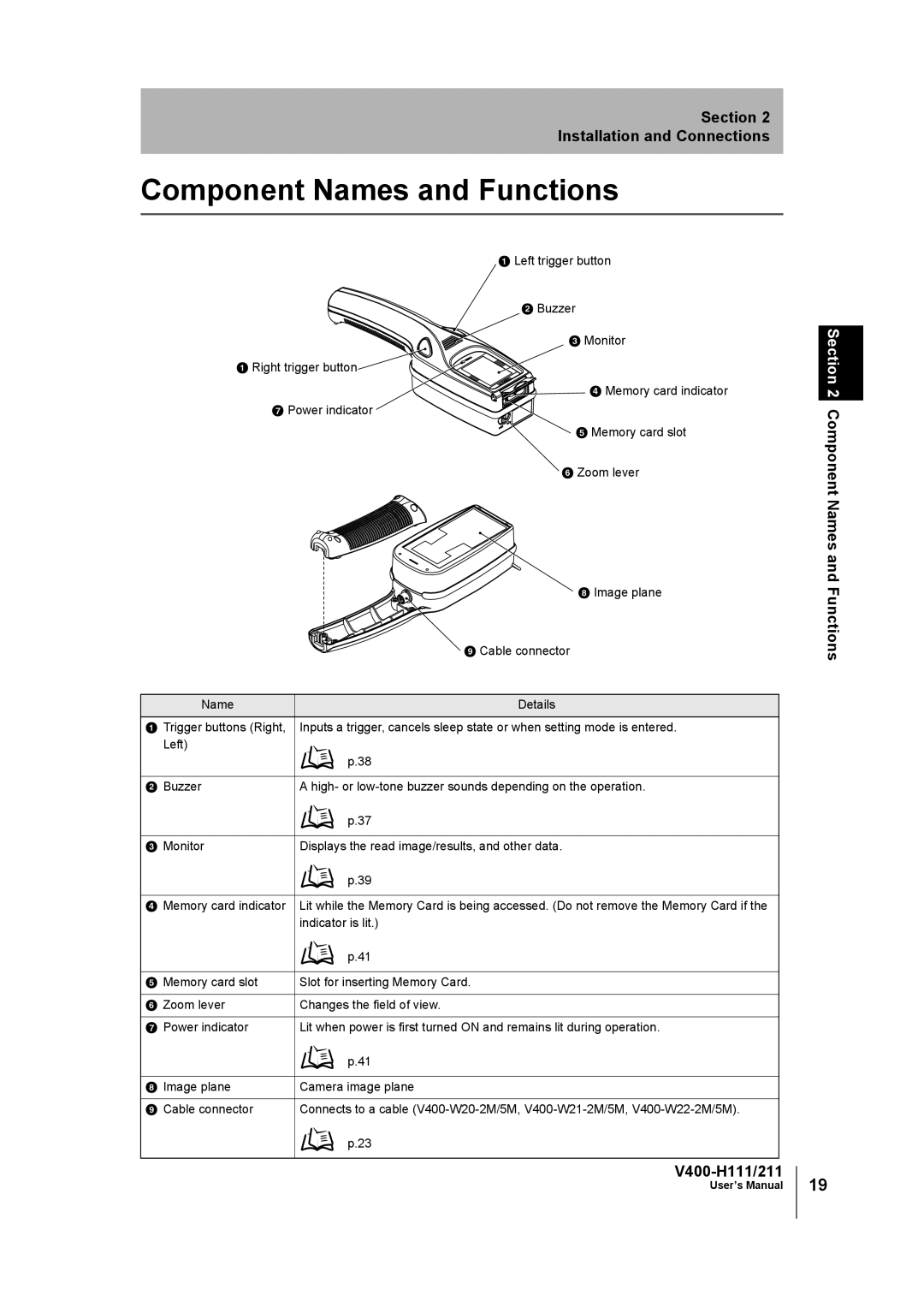
V400-H111 specifications
The Omron V400-H111 is a state-of-the-art vision sensor designed for a wide range of applications in industrial automation. This high-performing unit is renowned for its advanced features, which enable manufacturers to enhance productivity and improve quality control in their operations.One of the leading characteristics of the Omron V400-H111 is its sophisticated image processing capabilities. Equipped with an integrated camera, the vision sensor can perform complex inspections and analysis tasks with remarkable accuracy. The sensor utilizes a powerful algorithm that enables it to detect defects and anomalies in products almost instantaneously. This enhances the overall efficiency of production lines by allowing immediate corrective actions to be taken.
In addition to its robust inspection capabilities, the V400-H111 also offers exceptional flexibility in deployment. It features a compact design that can be easily integrated into various machinery and production setups. The sensor's high degree of adaptability enables it to perform optimally in different lighting conditions and on various surfaces, thus catering to diverse manufacturing environments.
The V400-H111 employs cutting-edge technology such as pattern matching and 1D/2D code reading. These technologies allow the sensor to identify and verify product features with extreme precision. Moreover, the sensor is capable of reading barcodes and QR codes, making it ideal for traceability applications in supply chain management.
Another important aspect of the Omron V400-H111 is its user-friendly interface. The system comes with an intuitive software platform that simplifies the setup and configuration processes. Even operators with limited technical knowledge can easily program the sensor for specific tasks, thereby reducing the training time and increasing operational efficiency.
The durability and reliability of the V400-H111 are further enhanced by its robust construction. Built to withstand the rigors of an industrial environment, the sensor is resistant to dust and moisture, ensuring long-term performance and reduced maintenance requirements.
In summary, the Omron V400-H111 vision sensor is a game-changing tool for manufacturers seeking to optimize their quality control systems. With its powerful image processing capabilities, flexible deployment options, advanced reading technologies, user-friendly interface, and robust construction, it stands out as a premier choice for enhancing production processes.

