1. Lay the equatorial mount on its side. Attach the tripod |
legs one at a time to the mount by sliding the screws |
installed in the tops of the tripod legs into the slots at the |
base of the mount and tightening the wing nuts finger- |
tight. Note that the accessory tray bracket attachment |
point on each leg should face inward. |
2. Tighten the leg lock knobs on the bottom braces of the |
tripod legs. For now, keep the legs at their shortest (fully |
retracted) length; you can extend them to a more desir- |
able length later, after the telescope is completely assem- |
bled. |
3. With the tripod legs now attached to the equatorial |
mount, stand the tripod upright (be careful!) and spread |
the legs apart enough to connect each end of the acces- |
sory tray bracket to the attachment point on each leg. |
Use the screw that comes installed in each attachment |
R.A. setting circle
Latitude scale
Latitude lock
h |
| is |
ax | ||
t |
| |
ig |
|
|
ascension |
| |
R |
|
|
Latitude adjustment
Azimuth lock knob
D
eclinationis x
a
Dec.
Dec. lock knob
Dec. setting circle
R.A. setting circle lock thumbscrew
R.A.
point to do this. First remove the screw using the supplied |
screwdriver, then line up one of the ends of the bracket |
with the attachment point and reinstall the screw. Make |
sure that the ribs in the plastic molding of the accessory |
tray bracket face downward. |
4. Now, with the accessory tray bracket attached, spread |
the tripod legs apart as far as they will go, until the brack- |
et is taut. Attach the accessory tray to the accessory tray |
bracket with the three wing screws already installed in the |
tray. This is done by pushing the wing screws up through |
the holes in the accessory tray bracket, and threading |
them into the holes in the accessory tray. |
5. Next, tighten the screws at the tops of the tripod legs, so |
the legs are securely fastened to the equatorial mount. |
Use the larger wrench and your fingers to do this. |
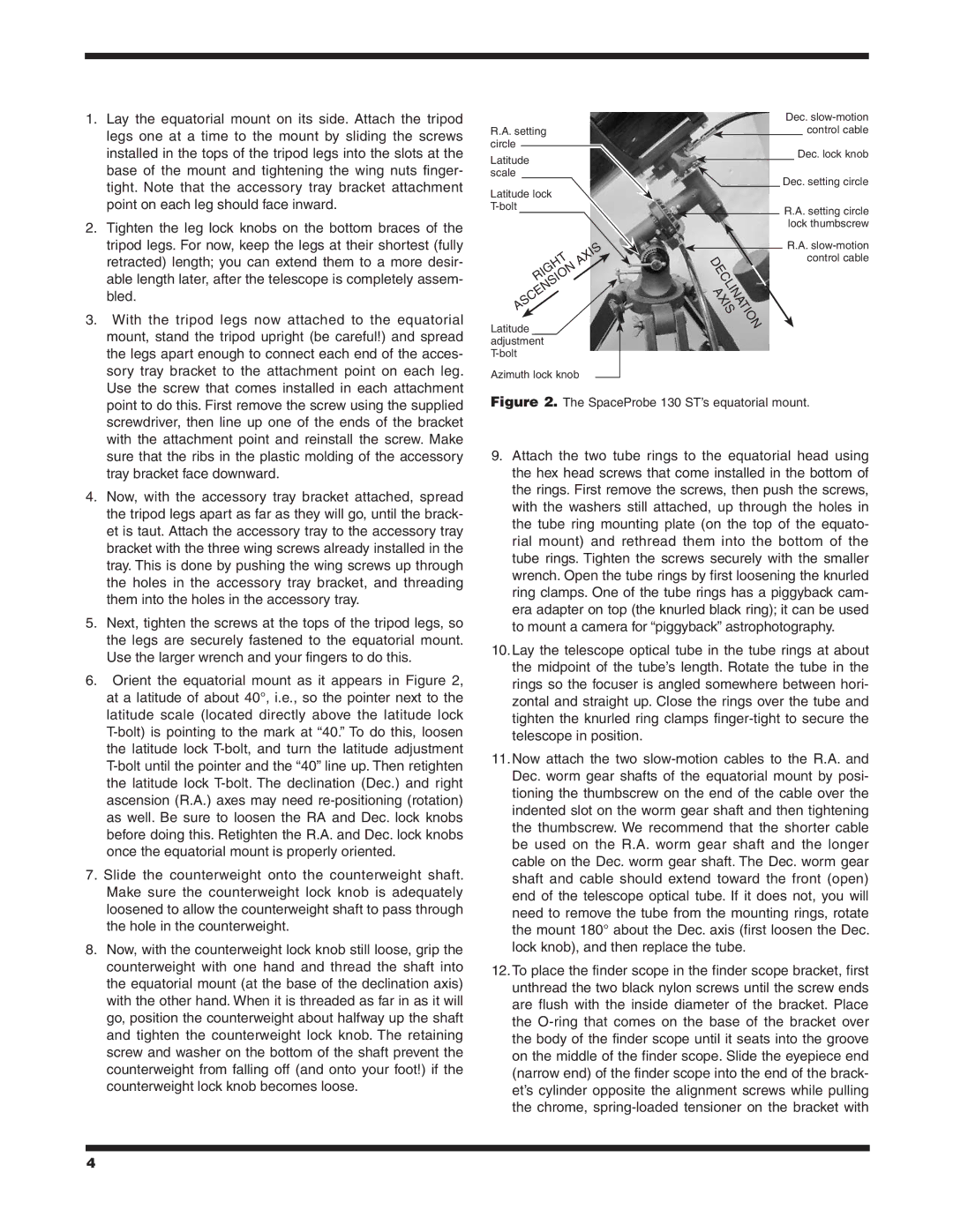
6. Orient the equatorial mount as it appears in Figure 2, |
at a latitude of about 40°, i.e., so the pointer next to the |
latitude scale (located directly above the latitude lock |
the latitude lock |
the latitude lock |
ascension (R.A.) axes may need |
as well. Be sure to loosen the RA and Dec. lock knobs |
before doing this. Retighten the R.A. and Dec. lock knobs |
once the equatorial mount is properly oriented. |
7. Slide the counterweight onto the counterweight shaft. |
Make sure the counterweight lock knob is adequately |
loosened to allow the counterweight shaft to pass through |
the hole in the counterweight. |
8. Now, with the counterweight lock knob still loose, grip the |
counterweight with one hand and thread the shaft into |
the equatorial mount (at the base of the declination axis) |
with the other hand. When it is threaded as far in as it will |
go, position the counterweight about halfway up the shaft |
and tighten the counterweight lock knob. The retaining |
screw and washer on the bottom of the shaft prevent the |
counterweight from falling off (and onto your foot!) if the |
counterweight lock knob becomes loose. |
Figure 2. The SpaceProbe 130 ST’s equatorial mount.
9.Attach the two tube rings to the equatorial head using the hex head screws that come installed in the bottom of the rings. First remove the screws, then push the screws, with the washers still attached, up through the holes in the tube ring mounting plate (on the top of the equato- rial mount) and rethread them into the bottom of the tube rings. Tighten the screws securely with the smaller wrench. Open the tube rings by first loosening the knurled ring clamps. One of the tube rings has a piggyback cam- era adapter on top (the knurled black ring); it can be used to mount a camera for “piggyback” astrophotography.
10.Lay the telescope optical tube in the tube rings at about the midpoint of the tube’s length. Rotate the tube in the rings so the focuser is angled somewhere between hori- zontal and straight up. Close the rings over the tube and tighten the knurled ring clamps
11.Now attach the two
12.To place the finder scope in the finder scope bracket, first unthread the two black nylon screws until the screw ends are flush with the inside diameter of the bracket. Place the
4