Manuals
/
Orion
/
Lawn and Garden
/
Telescope
Orion
8958 Collimating the Ritchey‑Chrétien, Image Orientation, Using the Collimating Eyepiece
Models:
8956
8958
1
6
9
9
Download
9 pages
49.57 Kb
2
3
4
5
6
7
8
9
Specification
Parts list
Warranty
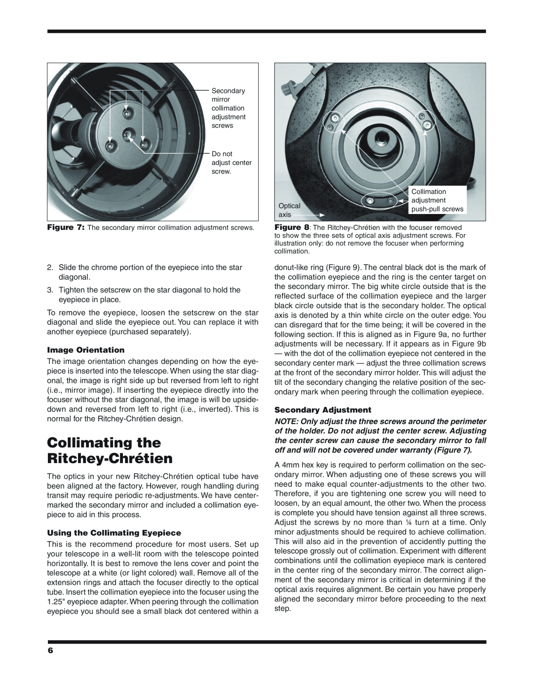
Secondary Adjustment
Star Testing
Focusing the Telescope
Page 6
Image 6
Page 5
Page 7
Page 6
Image 6
Page 5
Page 7
Contents
i n s t r u c t i o n M a n u a l
#8956 6 f/9 Ritchey-Chrétien Optical Tube Assembly
#8958 8 f/8 Ritchey-Chrétien Optical Tube Assembly
Orion Ritchey-Chrétien Astrographs
Parts List
Setting Up Your Telescope
Unpacking Your Telescope
2a 2b 2c 2d
Figures 2a-d Unpacking the Optical Tube
Grip-ring Focuser body Figure 3 Removing the focuser
Page
Inserting a Star Diagonal
Focusing the Telescope
Attaching a Finder Scope
Inserting an Eyepiece
Secondary Adjustment
Collimating the Ritchey‑Chrétien
Using the Collimating Eyepiece
Image Orientation
Optical Axis Adjustment
Star Testing
9b 9c
6 f/9 Ritchey-Chrétien
Care and Cleaning of the Optics
SpecificationsSpecifications
8 f/8 Ritchey-Chrétien
OrionTelescopes.com
Orion Telescopes & Binoculars
One-Year Limited Warranty
Customer Support Help Line
Top
Page
Image
Contents