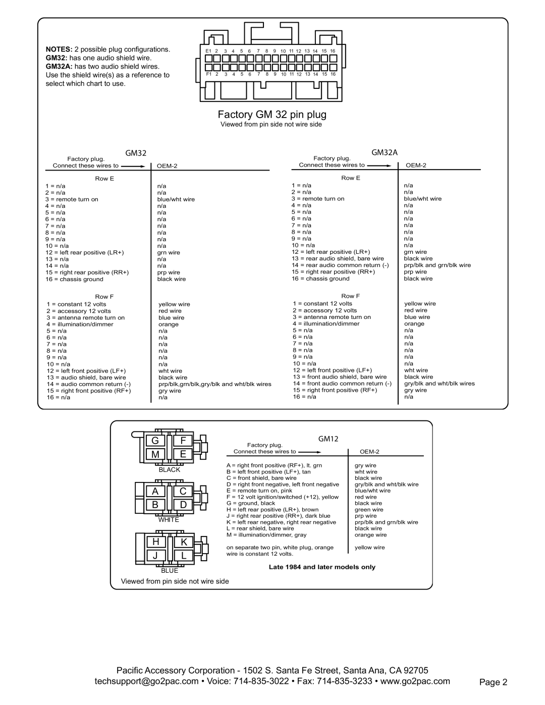
NOTES: 2 possible plug confi gurations.
GM32: has one audio shield wire.
GM32A: has two audio shield wires. Use the shield wire(s) as a reference to select which chart to use.
E1 2 3 4 5 6 7 8 9 10 11 12 13 14 15 16
F1 2 3 4 5 6 7 8 9 10 11 12 13 14 15 16
Factory GM 32 pin plug
Viewed from pin side not wire side
|
| GM32 |
|
| |
| Factory plug. |
|
| ||
| Connect these wires to |
|
|
| |
|
| ||||
| Row E |
|
| ||
1 | = n/a | n/a | |||
2 | = n/a | n/a | |||
3 | = remote turn on | blue/wht wire | |||
4 | = n/a | n/a | |||
5 | = n/a | n/a | |||
6 | = n/a | n/a | |||
7 | = n/a | n/a | |||
8 | = n/a | n/a | |||
9 | = n/a | n/a | |||
10 = n/a | n/a | ||||
12 = left rear positive (LR+) | grn wire | ||||
13 = n/a | n/a | ||||
14 = n/a | n/a | ||||
15 = right rear positive (RR+) | prp wire | ||||
16 = chassis ground | black wire | ||||
| Row F |
|
| ||
1 | = constant 12 volts | yellow wire | |||
2 | = accessory 12 volts | red wire | |||
3 | = antenna remote turn on | blue wire | |||
4 | = illumination/dimmer | orange | |||
5 | = n/a | n/a | |||
6 | = n/a | n/a | |||
7 | = n/a | n/a | |||
8 | = n/a | n/a | |||
9 | = n/a | n/a | |||
10 = n/a | n/a | ||||
12 = left front positive (LF+) | wht wire | ||||
13 = audio shield, bare wire | black wire | ||||
14 = audio common return | prp/blk,grn/blk,gry/blk and wht/blk wires | ||||
15 = right front positive (RF+) | gry wire | ||||
16 = n/a | n/a | ||||
|
|
|
|
|
|
|
| GM32A |
| |
| Factory plug. |
| ||
| Connect these wires to |
|
| |
|
| |||
| Row E |
| ||
1 | = n/a | n/a | ||
2 | = n/a | n/a | ||
3 | = remote turn on | blue/wht wire | ||
4 | = n/a | n/a | ||
5 | = n/a | n/a | ||
6 | = n/a | n/a | ||
7 | = n/a | n/a | ||
8 | = n/a | n/a | ||
9 | = n/a | n/a | ||
10 = n/a | n/a | |||
12 = left rear positive (LR+) | grn wire | |||
13 = rear audio shield, bare wire | black wire | |||
14 = rear audio common return | prp/blk and grn/blk wire | |||
15 = right rear positive (RR+) | prp wire | |||
16 = chassis ground | black wire | |||
| Row F |
| ||
1 | = constant 12 volts | yellow wire | ||
2 | = accessory 12 volts | red wire | ||
3 | = antenna remote turn on | blue wire | ||
4 | = illumination/dimmer | orange | ||
5 | = n/a | n/a | ||
6 | = n/a | n/a | ||
7 | = n/a | n/a | ||
8 | = n/a | n/a | ||
9 | = n/a | n/a | ||
10 = n/a | n/a | |||
12 = left front positive (LF+) | wht wire | |||
13 = front audio shield, bare wire | black wire | |||
14 = front audio common return | gry/blk and wht/blk wires | |||
15 = right front positive (RF+) | gry wire | |||
16 = n/a | n/a | |||
|
|
|
|
|
G ![]()
![]() F
F ![]()
![]()
M ![]()
![]() E
E ![]()
![]()
BLACK
A![]()
![]() C
C ![]()
![]()
![]()
B ![]()
![]() D
D ![]()
![]()
![]()
WHITE
HK
JL
BLUE
GM12
Factory plug. |
| ||
Connect these wires to |
|
|
|
| |||
A = right front positive (RF+), lt. grn | gry wire | ||
B = left front positive (LF+), tan | wht wire | ||
C = front shield, bare wire | black wire | ||
D = right front negative, left front negative | gry/blk and wht/blk wire | ||
E = remote turn on, pink | blue/wht wire | ||
F = 12 volt ignition/switched (+12), yellow | red wire | ||
G = ground, black | black wire | ||
H = left rear positive (LR+), brown | green wire | ||
J = right rear positive (RR+), dark blue | prp wire | ||
K = left rear negative, right rear negative | prp/blk and grn/blk wire | ||
L = rear shield, bare wire | black wire | ||
M = illumination/dimmer, gray | orange wire | ||
on separate two pin, white plug, orange | yellow wire | ||
wire is constant 12 volts. |
| ||
| |||
Late 1984 and later models only
Viewed from pin side not wire side
Pacifi c Accessory Corporation - 1502 S. Santa Fe Street, Santa Ana, CA 92705 |
|
techsupport@go2pac.com • Voice: | Page 2 |