MAX® 1500-UPS
• Learning IR Function • Critical Load Status Outlets • RS-232 Interface • Noise Filtration/Power Protection
FEATURES AND INCLUDED ACCESSORIES
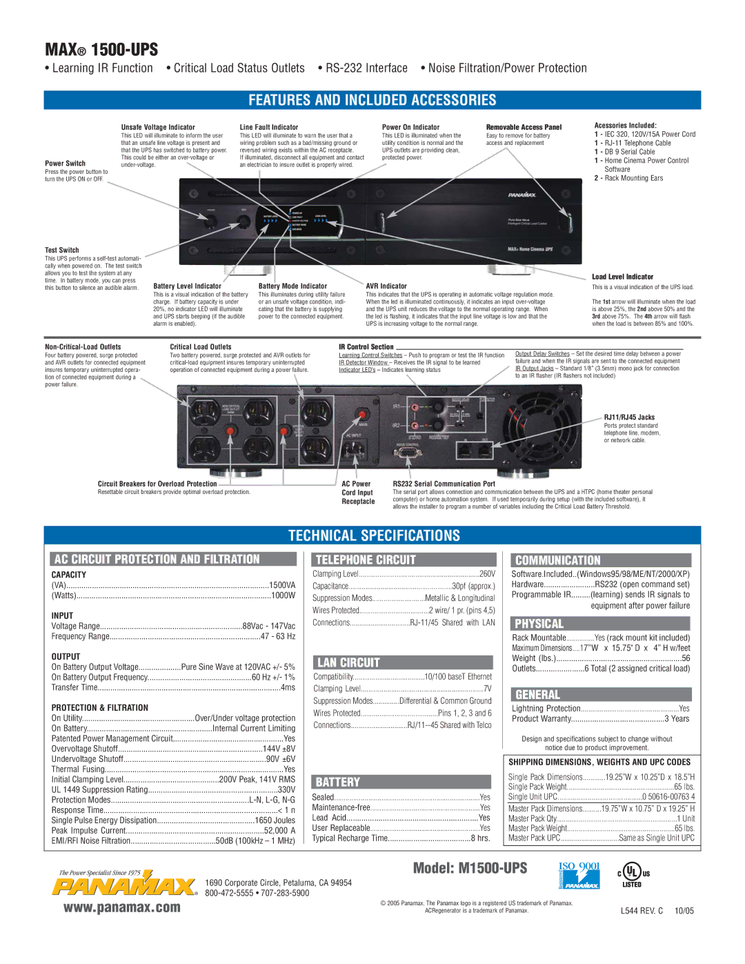
Power Switch
Press the power button to turn the UPS ON or OFF.
Unsafe Voltage Indicator
This LED will illuminate to inform the user that an unsafe line voltage is present and that the UPS has switched to battery power. This could be either an over-voltage or under-voltage.
Line Fault Indicator
This LED will illuminate to warn the user that a wiring problem such as a bad/missing ground or reversed wiring exists within the AC receptacle.
If illuminated, disconnect all equipment and contact an electrician to insure outlet is properly wired.
Power On Indicator | Removable Access Panel |
This LED is illuminated when the | Easy to remove for battery |
utility condition is normal and the | access and replacement |
UPS outlets are providing clean, | |
protected power. | |
Acessories Included:
1 - IEC 320, 120V/15A Power Cord
1 - RJ-11 Telephone Cable
1 - DB 9 Serial Cable
1 - Home Cinema Power Control
Software
2 - Rack Mounting Ears
Test Switch
This UPS performs a self-test automati- cally when powered on. The test switch allows you to test the system at any time. In battery mode, you can press this button to silence an audible alarm.
Battery Level Indicator
This is a visual indication of the battery charge. If battery capacity is under 20%, no indicator LED will illuminate and UPS starts beeping (if the audible alarm is enabled).
Battery Mode Indicator
This illuminates during utility failure or an unsafe voltage condition, indi- cating that the battery is supplying power to the connected equipment.
AVR Indicator
This indicates that the UPS is operating in automatic voltage regulation mode. When the led is illuminated continuously, it indicates an input over-voltage and the UPS unit reduces the voltage to the normal operating range. When the led is flashing, it indicates that the input line voltage is low and that the UPS is increasing voltage to the normal range.
Load Level Indicator
This is a visual indication of the UPS load.
The 1st arrow will illuminate when the load is above 25%, the 2nd above 50% and the 3rd above 75%. The 4th arrow will flash when the load is between 85% and 100%.
Non-Critical-Load Outlets
Four battery powered, surge protected and AVR outlets for connected equipment insures temporary uninterrupted opera- tion of connected equipment during a power failure.
Critical Load Outlets
Two battery powered, surge protected and AVR outlets for critical-load equipment insures temporary uninterrupted operation of connected equipment during a power failure.
IR Control Section
Learning Control Switches – Push to program or test the IR function IR Detector Window – Receives the IR signal to be learned Indicator LED’s – Indicates learning status
Output Delay Switches – Set the desired time delay between a power failure and when the IR signals are sent to the connected equipment IR Output Jacks – Standard 1/8” (3.5mm) mono jack for connection to an IR flasher (IR flashers not included)
RJ11/RJ45 Jacks
Ports protect standard telephone line, modem, or network cable.
Circuit Breakers for Overload Protection  AC Power
Resettable circuit breakers provide optimal overload protection.Cord Input
Receptacle
RS232 Serial Communication Port
The serial port allows connection and communication between the UPS and a HTPC (home theater personal computer) or home automation system. If used temporarily during setup (with the included software), it allows the installer to program a number of variables including the Critical Load Battery Threshold.
TECHNICAL SPECIFICATIONS
AC CIRCUIT PROTECTION AND FILTRATION
CAPACITY | |
(VA) | 1500VA |
(Watts) | 1000W |
INPUT | |
Voltage Range | 88Vac - 147Vac |
Frequency Range | 47 - 63 Hz |
OUTPUT | |
On Battery Output Voltage | Pure Sine Wave at 120VAC +/- 5% |
On Battery Output Frequency | 60 Hz +/- 1% |
Transfer Time | 4ms |
PROTECTION & FILTRATION | |
On Utility | Over/Under voltage protection |
On Battery | Internal Current Limiting |
Patented Power Management Circuit | Yes |
Overvoltage Shutoff | 144V ±8V |
Undervoltage Shutoff | 90V ±6V |
Thermal Fusing | Yes |
Initial Clamping Level | 200V Peak, 141V RMS |
UL 1449 Suppression Rating | 330V |
Protection Modes | L-N, L-G, N-G |
Response Time | < 1 n |
Single Pulse Energy Dissipation | 1650 Joules |
Peak Impulse Current | 52,000 A |
EMI/RFI Noise Filtration | 50dB (100kHz – 1 MHz) |
TELEPHONE CIRCUIT
Clamping Level | 260V |
Capacitance | 30pf (approx.) |
Suppression Modes | Metallic & Longitudinal |
Wires Protected | 2 wire/ 1 pr. (pins 4,5) |
Connections | RJ-11/45 Shared with LAN |
LAN CIRCUIT
Compatibility | 10/100 baseT Ethernet |
Clamping Level | 7V |
Suppression Modes | Differential & Common Ground |
Wires Protected | Pins 1, 2, 3 and 6 |
Connections | RJ/11--45 Shared with Telco |
BATTERY
Sealed | Yes |
Maintenance-free | Yes |
Lead Acid | Yes |
User Replaceable | Yes |
Typical Recharge Time | 8 hrs. |
COMMUNICATION
Software.Included..(Windows95/98/ME/NT/2000/XP)
Hardware | RS232 (open command set) |
Programmable IR | (learning) sends IR signals to |
| equipment after power failure |
PHYSICAL
Rack Mountable...............Yes (rack mount kit included)
Maximum Dimensions....17”W x 15.75" D x 4” H w/feet |
Weight (lbs.) | 56 |
Outlets | 6 Total (2 assigned critical load) |
GENERAL | |
Lightning Protection | Yes |
Product Warranty | 3 Years |
Design and specifications subject to change without
notice due to product improvement.
SHIPPING DIMENSIONS, WEIGHTS AND UPC CODES
Single Pack Dimensions | ............19.25”W x 10.25”D x 18.5”H |
Single Pack Weight | 65 lbs. |
Single Unit UPC | 0 50616-00763 4 |
Master Pack Dimensions | 19.75”W x 10.75” D x 19.25” H |
Master Pack Qty | 1 Unit |
Master Pack Weight | 65 lbs. |
Master Pack UPC | Same as Single Unit UPC |
Model: M1500-UPS
1690 Corporate Circle, Petaluma, CA 94954 800-472-5555 • 707-283-5900
www.panamax.com | © 2005 Panamax. The Panamax logo is a registered US trademark of Panamax. |
ACRegenerator is a trademark of Panamax. |