Main Unit Disassembly Process
Main Unit Disassembly Flowchart
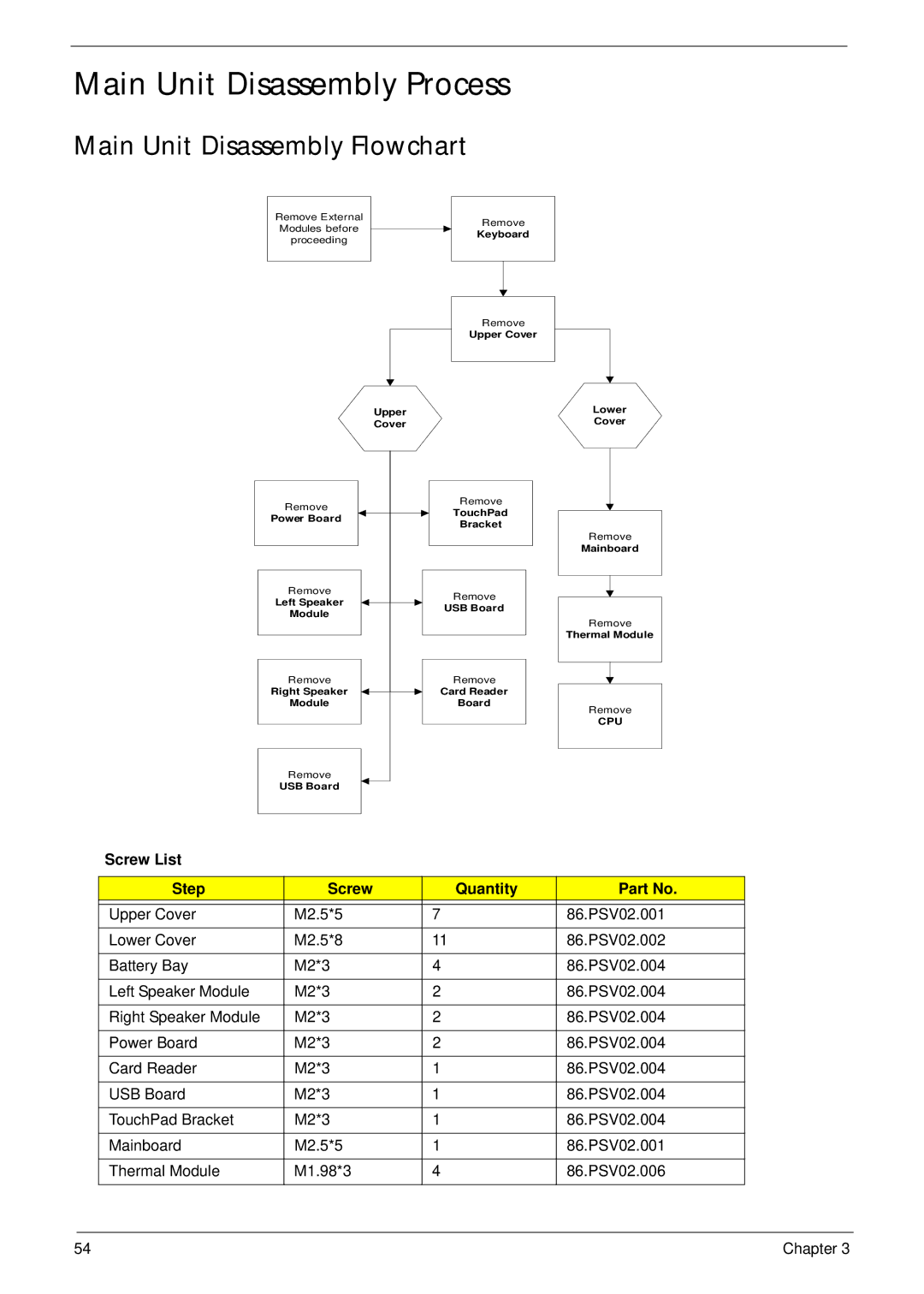
Remove External Modules before proceeding
Remove
Keyboard
Remove
Upper Cover
Upper
Cover
Remove
Power Board
Remove
Left Speaker
Module
Remove
Right Speaker
Module
Remove
USB Board
Remove
TouchPad Bracket
Remove
USB Board
Remove
Card Reader
Board
Lower
Cover
Remove
Mainboard
Remove
Thermal Module
Remove
CPU
Screw List
Step | Screw | Quantity | Part No. |
|
|
|
|
Upper Cover | M2.5*5 | 7 | 86.PSV02.001 |
Lower Cover | M2.5*8 | 11 | 86.PSV02.002 |
|
|
|
|
Battery Bay | M2*3 | 4 | 86.PSV02.004 |
|
|
|
|
Left Speaker Module | M2*3 | 2 | 86.PSV02.004 |
|
|
|
|
Right Speaker Module | M2*3 | 2 | 86.PSV02.004 |
|
|
|
|
Power Board | M2*3 | 2 | 86.PSV02.004 |
|
|
|
|
Card Reader | M2*3 | 1 | 86.PSV02.004 |
|
|
|
|
USB Board | M2*3 | 1 | 86.PSV02.004 |
|
|
|
|
TouchPad Bracket | M2*3 | 1 | 86.PSV02.004 |
|
|
|
|
Mainboard | M2.5*5 | 1 | 86.PSV02.001 |
|
|
|
|
Thermal Module | M1.98*3 | 4 | 86.PSV02.006 |
|
|
|
|
54 | Chapter 3 |