AHR5
NOTES
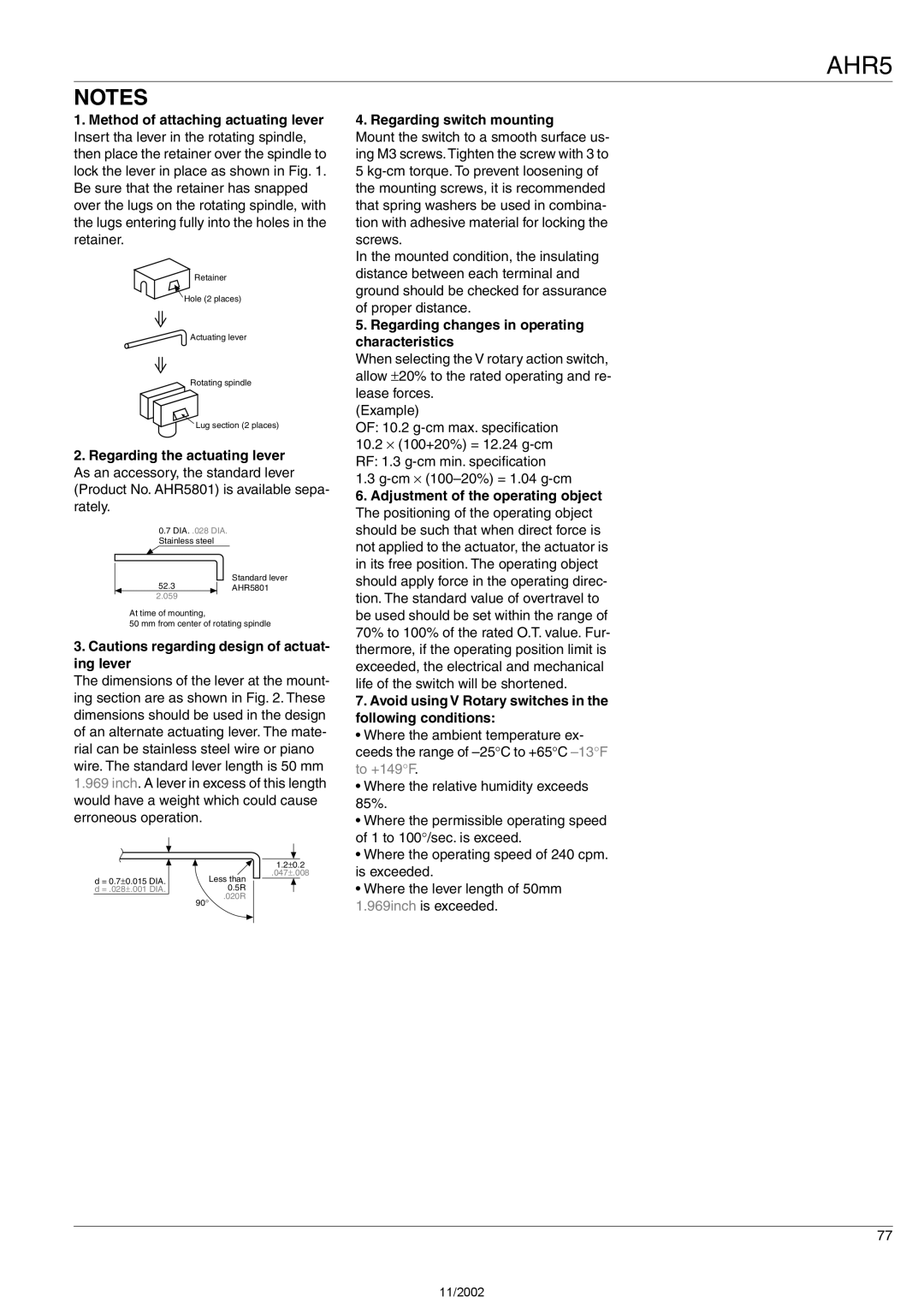
1.Method of attaching actuating lever Insert tha lever in the rotating spindle, then place the retainer over the spindle to lock the lever in place as shown in Fig. 1. Be sure that the retainer has snapped over the lugs on the rotating spindle, with the lugs entering fully into the holes in the retainer.
Retainer
Hole (2 places)
Actuating lever
Rotating spindle
Lug section (2 places)
2.Regarding the actuating lever As an accessory, the standard lever (Product No. AHR5801) is available sepa- rately.
0.7DIA. .028 DIA. Stainless steel
Standard lever
52.3AHR5801
2.059
At time of mounting,
50 mm from center of rotating spindle
3.Cautions regarding design of actuat- ing lever
The dimensions of the lever at the mount- ing section are as shown in Fig. 2. These dimensions should be used in the design of an alternate actuating lever. The mate- rial can be stainless steel wire or piano wire. The standard lever length is 50 mm 1.969 inch. A lever in excess of this length would have a weight which could cause erroneous operation.
|
|
|
|
|
| |
|
| 1.2±0.2 | ||||
|
| .047±.008 | ||||
d = 0.7±0.015 DIA. |
| Less than |
|
|
|
|
|
|
|
|
| ||
d = .028±.001 DIA. |
| 0.5R |
|
|
|
|
| 90° | .020R |
|
|
|
|
|
|
|
|
|
| |
|
|
|
|
|
|
|
4. Regarding switch mounting
Mount the switch to a smooth surface us- ing M3 screws. Tighten the screw with 3 to 5
In the mounted condition, the insulating distance between each terminal and ground should be checked for assurance of proper distance.
5.Regarding changes in operating characteristics
When selecting the V rotary action switch, allow ±20% to the rated operating and re- lease forces.
(Example)
OF: 10.2
RF: 1.3
1.3
6.Adjustment of the operating object The positioning of the operating object should be such that when direct force is not applied to the actuator, the actuator is in its free position. The operating object should apply force in the operating direc- tion. The standard value of overtravel to be used should be set within the range of 70% to 100% of the rated O.T. value. Fur- thermore, if the operating position limit is exceeded, the electrical and mechanical life of the switch will be shortened.
7.Avoid using V Rotary switches in the following conditions:
• Where the ambient temperature ex- ceeds the range of
• Where the relative humidity exceeds 85%.
• Where the permissible operating speed of 1 to 100°/sec. is exceed.
• Where the operating speed of 240 cpm. is exceeded.
• Where the lever length of 50mm 1.969inch is exceeded.
77
11/2002