Controls and their Functions
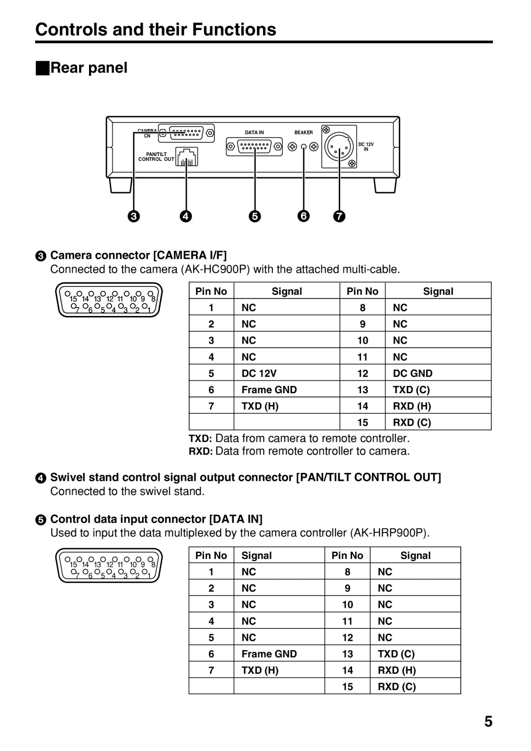
_Rear panel
CAMERA | DATA IN | BEAKER |
CN |
|
|
PAN/TILT
CONTROL OUT
DC 12V
IN
3 | 4 | 5 | 6 | 7 |
3Camera connector [CAMERA I/F]
Connected to the camera
15 14 13 12 11 10 9 8
7 6 5 4 3 2 1
Pin No | Signal | Pin No | Signal |
1 | NC | 8 | NC |
2 | NC | 9 | NC |
3 | NC | 10 | NC |
4 | NC | 11 | NC |
5 | DC 12V | 12 | DC GND |
6 | Frame GND | 13 | TXD (C) |
7 | TXD (H) | 14 | RXD (H) |
|
| 15 | RXD (C) |
|
|
|
|
TXD: Data from camera to remote controller.
RXD: Data from remote controller to camera.
4Swivel stand control signal output connector [PAN/TILT CONTROL OUT] Connected to the swivel stand.
5Control data input connector [DATA IN]
Used to input the data multiplexed by the camera controller
15 | 14 | 13 | 12 11 | 10 | 9 |
| Pin No | Signal | Pin No | Signal | |
| 8 | NC | 8 | NC | |||||||
7 | 6 | 5 | 4 | 3 | 2 |
| 1 | 1 | |||
|
|
|
|
|
|
|
| 2 | NC | 9 | NC |
|
|
|
|
|
|
|
| 3 | NC | 10 | NC |
|
|
|
|
|
|
|
| 4 | NC | 11 | NC |
|
|
|
|
|
|
|
| 5 | NC | 12 | NC |
|
|
|
|
|
|
|
| 6 | Frame GND | 13 | TXD (C) |
|
|
|
|
|
|
|
| 7 | TXD (H) | 14 | RXD (H) |
|
|
|
|
|
|
|
|
|
| 15 | RXD (C) |
5