G | Installation Guide (Continued) |
|
|
| G | ||
E |
|
|
|
|
|
| E |
N |
|
|
|
|
|
| N |
L |
|
|
|
|
|
| L |
I |
|
|
|
|
|
| I |
S | Speakers | ❐ Final Checks | ❐ Installation Procedures |
|
| S | |
H |
|
| H | ||||
11 | Connect the speaker wires. See the wiring diagram | 1. | Make sure that all wires are properly connected | First complete the electrical connections, and |
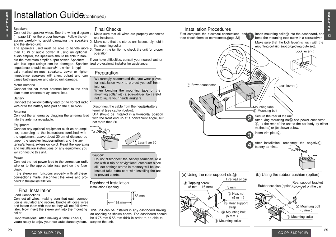
| Insert mounting collar 1 into the dashboard, and | 12 |
(➡ page 32) for the proper hookups. Follow the di- |
| and insulated. | then check them for correctness. (➡ page 32) | 1bend the mounting tabs out with a screwdriver. | |||
|
|
| |||||
| agram carefully to avoid damaging the speakers | 2. | Make sure that the stereo unit is securely held in |
|
| Make sure that the lock lever (§) is flush with the |
|
| and the stereo unit. |
|
|
| |||
|
| the mounting collar. |
|
| mounting collar 1 (not projecting outward). |
| |
| The speakers used must be able to handle more |
|
|
|
| ||
| 3. Turn on the ignition to check the unit for proper |
|
| Lock lever (§) |
| ||
| than 45 W of audio power. If using an optional |
|
|
| |||
|
| operation. |
|
|
| ||
| audio amplifier, the speakers should be able to han- |
|
|
|
|
| |
| If you have difficulties, consult your nearest author- |
|
|
|
| ||
| dle the maximum amplifier output power. Speakers |
|
|
|
| ||
| with low input ratings can be damaged. Speaker | ized professional installer for assistance. |
|
|
|
| |
| impedance should measure |
|
|
|
|
|
|
| cally marked on most speakers. Lower or higher | ❐ Preparation |
|
|
|
| |
| impedance speakers will affect output and can | ≥We strongly recommend that you wear gloves |
|
|
|
| |
| cause both speaker and stereo unit damage. |
|
|
|
| ||
| Motor Antenna |
| for installation work to protect yourself from | 6 Power connector |
| Lock lever (§) |
|
|
| injuries. |
|
| |||
| Connect the car motor antenna lead to the dark | ≥When bending the mounting tabs of the |
|
|
|
| |
| blue motor antenna relay control lead. |
|
|
|
| ||
|
| mounting collar with a screwdriver, be careful |
|
|
|
| |
| Battery |
|
|
|
|
| |
|
| not to injure your hands and fingers. |
|
|
|
| |
| Connect the yellow battery lead to the correct radio |
|
|
|
|
|
|
| wire or to the battery fuse port on the fuse block. | ≥Disconnect the cable from the negative - battery |
| Mounting tabs |
| ||
| Antenna |
| terminal (see caution below). |
| 5 Mounting bolt |
| |
| Connect the antenna by plugging the antenna lead | ≥Unit should be installed in a horizontal position |
|
| Secure the rear of the unit. |
| |
|
| with the front end up at a convenient angle, but |
|
|
| ||
| into the antenna receptacle. |
|
| 2After fixing mounting bolt 5 and power connector |
| ||
|
| not more than 30o. |
|
| |||
| Equipment |
|
|
| 6, fix the rear of the unit to the car body by either |
| |
|
|
|
|
|
| ||
|
|
|
|
| method (a) or (b) shown below. |
| |
| Connect any optional equipment such as an ampli- |
|
|
|
|
| |
|
|
|
|
|
|
| |
| fier, according to the instructions furnished with |
|
|
| 3 | Insert trim plate 7. |
|
| the equipment. Leave about 30 cm of distance be- |
|
|
|
|
| |
| tween the speaker leads/amplifier unit and the an- |
| Less than 30x |
|
| After installation, reconnect the negative - |
|
| tenna/antenna extension cord. Read the operating |
|
|
|
| ||
|
|
|
| 4battery terminal. |
| ||
| and installation instructions of any equipment you |
|
|
|
| ||
|
|
|
|
|
|
| |
will connect to this unit.
Power | Caution: |
|
|
|
| |
≥Do not disconnect the battery terminals of a |
|
|
|
| ||
Connect the red power lead to the correct car radio |
|
|
|
| ||
car with a trip or navigational computer since |
|
|
|
| ||
wire or to the appropriate fuse port on the fuse |
|
|
|
| ||
all user settings stored in memory will be lost. |
|
|
|
| ||
block. |
|
|
|
| ||
Instead take extra care with installing the unit |
|
|
|
| ||
If the stereo unit functions properly with all these | (a) Using the rear support strap 3 | (b) Using the rubber cushion (option) | ||||
to prevent shorts. | ||||||
connections made, disconnect the wires and pro- |
|
| Fire wall of car |
|
| |
ceed to the final installation. | Dashboard Installation | 4 Tapping screw |
| Rear support bracket | ||
|
| |||||
|
| Rubber cushion (option) | ||||
❐ Final Installation | Installation Opening | (5 mm·a16 mm) | 3 mm· | (provided on the car) | ||
|
| 2 Hex. nut |
|
| ||
Lead Connections | 53 mm |
|
|
| ||
| (5 mm·) |
|
| |||
Connect all wires, making sure that each connec- |
|
|
|
| ||
tion is insulated and secure. Bundle all loose wires | 182 mm |
| 3 Rear support |
|
| |
and fasten them with tape so they will not fall down | This unit can be installed in any dashboard having |
| strap |
| 5 Mounting bolt | |
later. Now insert the stereo unit into the mounting |
| 5 Mounting bolt |
| (5 mm·) | ||
collar. | an opening as shown above. The dashboard should |
|
|
| ||
|
| (5 mm·) | 1 Mounting collar | |||
Congratulations! After making a few final checks, | be 4.75 mmj5.56 mm thick in order to be able to |
| ||||
| 1 Mounting collar |
|
| |||
you’re ready to enjoy your new auto stereo system. | support the unit. |
|
|
| ||
28 |
|
|
|
| 29 | |
|
|
| ||||